0 10v To 4 20ma Signal Converter
Many modern home automation systems rely on accurate signal transmission between sensors and controllers. One common component facilitating this communication is a 0-10V to 4-20mA signal converter. These converters translate a voltage signal (0-10 volts, often representing things like temperature or pressure) into a current signal (4-20 milliamps), which is less susceptible to noise and voltage drops over longer distances. When these converters malfunction, you might experience issues with your home's climate control, irrigation, or other automated systems. This guide provides a methodical approach to troubleshooting these converters, helping you identify and resolve common problems, and knowing when to call in a professional.
Understanding the Basics
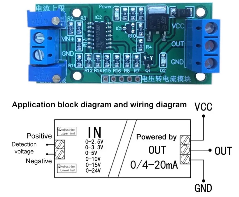
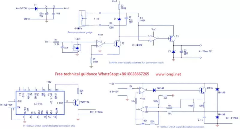
Before diving into troubleshooting, it's crucial to understand the basic function of the converter. It takes a 0-10V input signal and outputs a 4-20mA signal. A 0V input should result in a 4mA output, and a 10V input should result in a 20mA output. Anything in between should be a linear scaling (e.g., 5V input should be 12mA output). This linear relationship is key to proper operation. Any deviation indicates a potential problem.
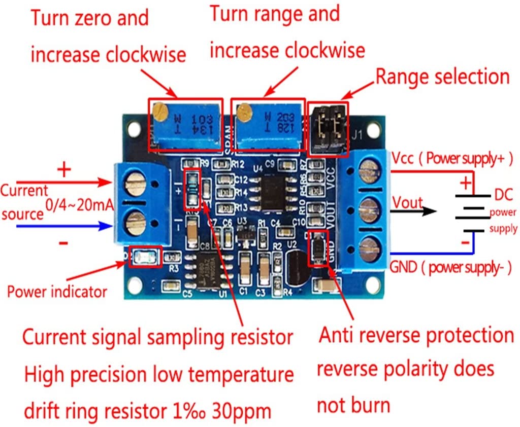
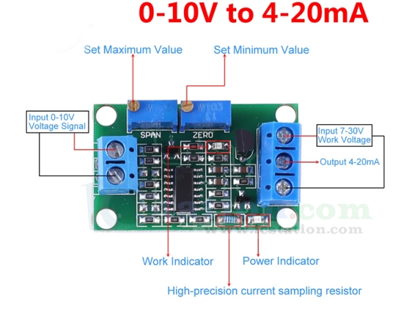
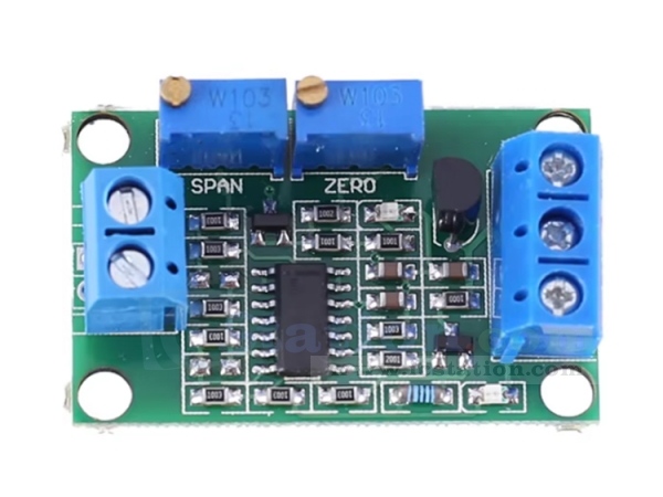
These converters usually have several terminals: power supply input (typically 24V DC, but check the manufacturer's specifications), 0-10V input, and 4-20mA output. Always verify the correct wiring according to the converter's datasheet. Incorrect wiring is a common cause of malfunction.
Common Homeowner Problem: Inaccurate Temperature Readings
Let's consider a common scenario: your smart thermostat displays an inaccurate temperature. This could be caused by a faulty temperature sensor, wiring problems, or, importantly, a malfunctioning 0-10V to 4-20mA signal converter linking the temperature sensor to the thermostat. The thermostat receives a current signal, translates it back to a temperature reading, and displays it. If the converter isn't accurately translating the sensor's voltage output, the displayed temperature will be incorrect.
Step-by-Step Troubleshooting Guide
Step 1: Safety First!
Before you begin, ensure the power supply to the converter and related equipment is turned off and locked out/tagged out. This is crucial to prevent electrical shock. Double-check with a multimeter to confirm the power is indeed off before proceeding. Never work on live circuits.
Step 2: Visual Inspection
Carefully inspect the converter for any obvious signs of damage. Look for:
- Burn marks or scorching
- Loose wiring or frayed connections
- Corrosion or rust, especially at the terminals
- Physical damage to the enclosure
- Swollen or leaking capacitors (if visible)
If you find any of these signs, the converter might be beyond repair and require replacement. Make notes of any visual anomalies that could assist in troubleshooting.
Step 3: Check the Wiring
Verify the wiring connections against the manufacturer's datasheet. Ensure:
- Wires are securely connected to the correct terminals.
- The correct polarity is observed for the power supply (positive and negative).
- No wires are loose or shorted. Gently tug on each wire to ensure it's firmly seated in the terminal.
- The wire gauge is appropriate for the current and voltage.
- Check for continuity on all wires. Use a multimeter to check that all the wires are not cut or broken in some place.
Sometimes, a loose or incorrect connection is the only problem. Double-check everything before moving on.
Step 4: Verify the Power Supply
Using a multimeter, check the voltage of the power supply connected to the converter. It must match the converter's specified input voltage (typically 24V DC, but confirm this). A low or unstable power supply can cause the converter to malfunction.
Set your multimeter to DC voltage mode and measure the voltage at the converter's power input terminals. If the voltage is significantly lower than the specified value, the power supply itself may be faulty and need to be replaced.
Step 5: Test the 0-10V Input Signal
Disconnect the existing sensor from the converter's input. Use a variable voltage source (e.g., a signal generator or a potentiometer connected to a stable power supply) to simulate a 0-10V input signal. This allows you to isolate the converter from the sensor and test its functionality directly.
Connect the variable voltage source to the converter's 0-10V input terminals. Gradually increase the voltage from 0V to 10V, using a multimeter to accurately monitor the voltage you're applying.
Step 6: Measure the 4-20mA Output Signal
Using a multimeter in current mode (mA), measure the output current of the converter. Ensure your multimeter is connected in series with the load (e.g., the input of your thermostat or controller). Be extremely careful when measuring current, as incorrect connections can damage your multimeter or the circuit.
For each input voltage value (0V, 2.5V, 5V, 7.5V, 10V), record the corresponding output current. Compare these values to the expected values based on the linear relationship (0V = 4mA, 10V = 20mA, etc.).
Step 7: Analyzing the Results
Here's how to interpret your measurements:
- If the output current is consistently stuck at a fixed value (e.g., 4mA or 20mA) regardless of the input voltage: The converter is likely faulty and needs to be replaced.
- If the output current is erratic or unstable: There could be a problem with the converter's internal circuitry, the power supply, or noise interference. Try filtering the power.
- If the output current is linearly proportional to the input voltage but offset: The converter may need calibration (if it has calibration adjustments) or may be faulty. An example: if 0V input yields 6mA output and 10V input yields 22mA output.
- If the output current is correct for some input voltages but not others: This suggests a non-linear problem within the converter, likely requiring replacement.
- If the voltage from the power supply is wrong: Repair or replace the power supply.
- If the wiring is incorrect: Rewire the sensor with the correct wiring diagram.
Step 8: Simple DIY Fixes
Based on your findings, you might be able to perform some simple fixes:
- Tighten Loose Connections: Use a screwdriver to ensure all wiring connections are secure.
- Replace Faulty Wiring: If you find damaged wiring, replace it with appropriately sized wire.
- Clean Corroded Terminals: Use a wire brush or contact cleaner to remove corrosion from the terminals.
- Replace the Power Supply: If the power supply is faulty, replace it with a compatible model.
Always double-check your work after making any adjustments and re-test the converter to ensure it's functioning correctly.
When to Call a Professional
While this guide covers common troubleshooting steps, certain situations require professional intervention. Call a qualified electrician or instrumentation technician if:
- You are uncomfortable working with electrical wiring or circuits.
- You suspect the converter has internal component failure (e.g., burnt components, leaking capacitors).
- You are unable to isolate the problem using the steps outlined in this guide.
- The converter requires calibration, and you do not have the necessary equipment or expertise.
- You are working in a hazardous environment or with high-voltage equipment.
- You suspect that the problem stems from the sensor itself.
Attempting to repair complex electronic components without proper training can be dangerous and can further damage the equipment. It's always better to err on the side of caution and seek professional help when needed. Replacing the converter might be the best option if the damage seems too extensive.
Preventative Maintenance
To minimize the likelihood of future problems, consider these preventative measures:
- Regular Visual Inspections: Periodically inspect the converter and wiring for any signs of damage or wear.
- Ensure Proper Ventilation: Make sure the converter is installed in a well-ventilated area to prevent overheating.
- Protect from Moisture: Protect the converter from moisture and humidity, which can cause corrosion.
- Use Surge Protection: Install surge protection devices to protect the converter from voltage spikes.
By following these preventative measures, you can extend the life of your 0-10V to 4-20mA signal converter and ensure reliable operation of your home automation system.
Final Thoughts
Troubleshooting a 0-10V to 4-20mA signal converter can seem daunting, but by following this methodical approach, you can often identify and resolve common problems yourself. Remember to prioritize safety, double-check your work, and don't hesitate to seek professional help when needed. With a little patience and attention to detail, you can keep your home automation system running smoothly.