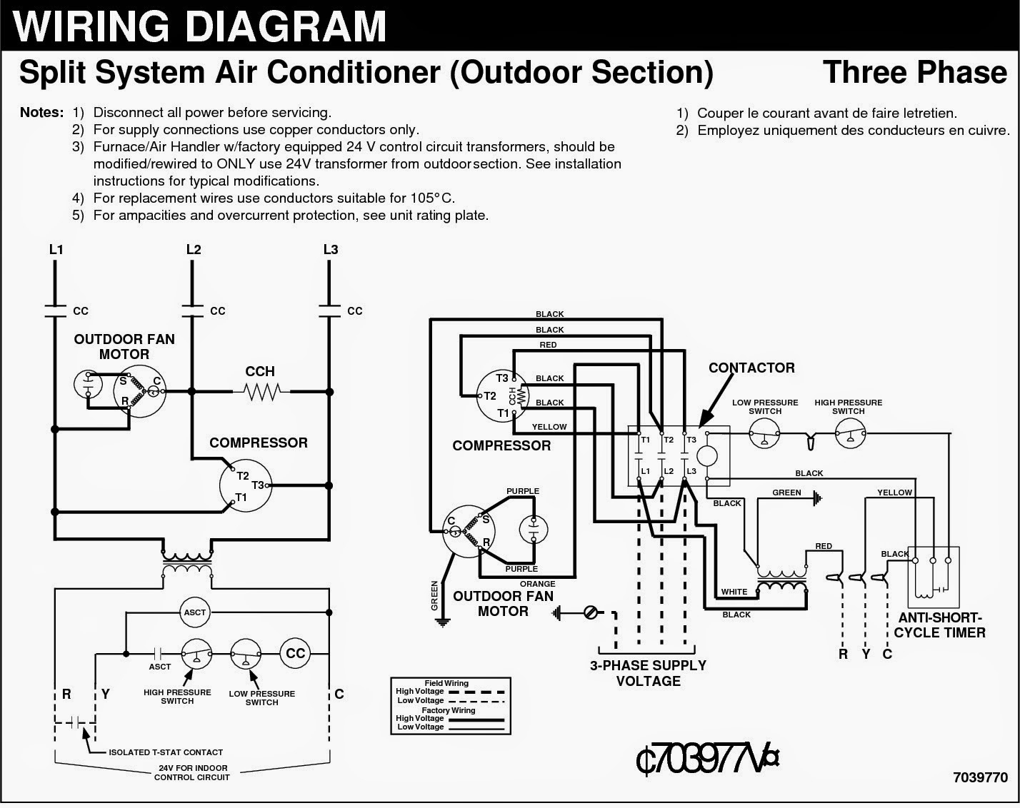
Air Compressor 3 Phase Wiring Diagram

Understanding the intricacies of a 3-phase air compressor wiring diagram is crucial for anyone involved in industrial maintenance, electrical engineering, or even advanced DIY projects. This guide breaks down the complexities of these diagrams into manageable, easy-to-understand segments, ensuring you gain a solid grasp of the subject matter.
What is 3-Phase Power?
Before diving into the wiring diagram, it's essential to understand 3-phase power. Imagine electricity flowing like water through pipes. In a single-phase system, you have one "pipe" pushing and pulling the water (electricity). In a 3-phase system, you have three "pipes," each pushing and pulling, but slightly out of sync with each other. This staggered delivery provides a smoother, more consistent power flow, making it ideal for heavy-duty equipment like air compressors.
Key Advantages of 3-Phase Power:
- More Efficient: Delivers more power with smaller wires compared to single-phase for the same voltage.
- Smoother Operation: Provides a constant power supply, reducing vibrations and extending the lifespan of motors.
- Higher Starting Torque: Essential for starting large motors used in air compressors.
Decoding the 3-Phase Air Compressor Wiring Diagram
A 3-phase air compressor wiring diagram is a schematic representation of the electrical connections within the compressor system. It shows how various components, such as the motor, starter, pressure switch, and safety devices, are interconnected. Understanding this diagram is vital for troubleshooting, maintenance, and safe operation.
Common Components in a 3-Phase Air Compressor Wiring Diagram:
- Power Source (L1, L2, L3): Represents the three incoming power lines.
- Main Disconnect Switch: Allows for safely disconnecting power to the compressor.
- Overload Protection: Circuit breakers or fuses that protect the motor from overcurrent conditions. Think of them as safety valves, tripping to prevent damage.
- Motor Starter (Contactor): An electromagnetic switch that controls the flow of power to the motor. It's typically controlled by the pressure switch.
- Pressure Switch: Monitors the air pressure in the tank and signals the motor starter to turn the motor on or off to maintain the desired pressure range.
- Motor: The workhorse of the compressor, converting electrical energy into mechanical energy to drive the pump.
- Thermal Overloads: Protective devices built into the motor starter that trip and shut down the motor if it overheats.
- Control Transformer (Optional): Steps down the voltage for the control circuit (e.g., 480V to 120V).
- Capacitors (For some models): Used to improve the motor's power factor and starting torque.
- Ground Connection (Earth): A crucial safety feature, providing a path for fault current to flow to ground, tripping the circuit breaker and preventing electrical shock.
Understanding Wiring Symbols
Wiring diagrams use standardized symbols to represent different electrical components. Familiarizing yourself with these symbols is crucial for accurate interpretation. Here are some common examples:
- Resistor: A zigzag line.
- Capacitor: Two parallel lines.
- Inductor: A coil-shaped symbol.
- Switch: A line with a break and a connecting line.
- Motor: A circle with the letter "M" inside.
- Transformer: Two coils next to each other.
- Ground: A series of horizontal lines decreasing in size.
Step-by-Step Guide to Interpreting a 3-Phase Wiring Diagram
Let's break down the process of interpreting a 3-phase air compressor wiring diagram:
- Identify the Power Source: Locate the L1, L2, and L3 lines, representing the three phases of incoming power. These are usually at the top of the diagram.
- Trace the Power Flow: Follow the lines from the power source to the main disconnect switch. This switch allows you to cut off all power to the compressor for maintenance or emergencies.
- Examine Overload Protection: After the disconnect switch, you'll typically find circuit breakers or fuses. Trace the lines through these devices to the motor starter.
- Analyze the Motor Starter: The motor starter (contactor) is a key component. It has a coil that, when energized, closes contacts to send power to the motor. The pressure switch usually controls the coil of the motor starter.
- Follow the Control Circuit: The control circuit operates the motor starter. Trace the wiring from the power source (often a control transformer if one is used) through the pressure switch, thermal overloads, and back to the motor starter coil. When the pressure in the tank drops below a setpoint, the pressure switch closes, energizing the motor starter coil and starting the motor. If the motor overheats, the thermal overloads trip, breaking the circuit and stopping the motor.
- Locate the Motor: The motor receives power from the motor starter. Ensure that the motor windings are correctly connected (usually labeled U, V, and W or T1, T2, and T3).
- Verify Ground Connection: The ground wire should be connected to the compressor frame and motor housing. This is a critical safety feature.
Common 3-Phase Wiring Configurations
Two primary wiring configurations are used in 3-phase systems: Wye (Y) and Delta (Δ). Each configuration has different characteristics and voltage relationships.
Wye (Y) Configuration
In a Wye configuration, one end of each of the three windings is connected to a common point called the neutral point. The other ends of the windings are connected to the three-phase power lines (L1, L2, L3).
Characteristics of Wye Configuration:
- Provides both phase-to-phase voltage (voltage between any two of the three lines) and phase-to-neutral voltage (voltage between any line and the neutral point).
- Generally used for power distribution and applications requiring both voltage levels.
- The voltage from line to neutral is equal to the line-to-line voltage divided by the square root of 3.
Delta (Δ) Configuration
In a Delta configuration, the three windings are connected in a closed loop, forming a triangle. Each corner of the triangle is connected to one of the three-phase power lines (L1, L2, L3).
Characteristics of Delta Configuration:
- Provides only phase-to-phase voltage. There is no neutral point in a standard Delta configuration.
- Often used for powering motors and other heavy-duty equipment.
- The voltage from line to line is equal to the voltage across each winding.
The choice between Wye and Delta depends on the specific application and the voltage requirements of the equipment.
Troubleshooting Common Wiring Issues
When your 3-phase air compressor isn't working correctly, the wiring diagram becomes your best friend. Here are some common issues and how to troubleshoot them:
- Motor Won't Start:
- Check Power Supply: Ensure all three phases are present and have the correct voltage. Use a multimeter to verify.
- Inspect Overload Protection: Check if the circuit breakers or fuses have tripped. Reset them if necessary.
- Examine Pressure Switch: Make sure the pressure switch is functioning correctly. Use a multimeter to check for continuity when the pressure is below the setpoint.
- Test Motor Starter: Check the motor starter coil for continuity. If the coil is open, the starter needs to be replaced. Also, check the contacts for burning or pitting.
- Verify Motor Windings: Use a multimeter to check the resistance of the motor windings. Open windings indicate a faulty motor.
- Motor Overheats:
- Check Thermal Overloads: These devices are designed to protect the motor from overheating. If they have tripped, investigate the cause of the overheating (e.g., blocked air vents, low voltage, excessive load).
- Inspect Motor Fan: Ensure the motor fan is working properly to cool the motor.
- Verify Voltage Balance: Uneven voltage across the three phases can cause the motor to overheat. Check the voltage on each phase using a multimeter.
- Compressor Runs But Doesn't Build Pressure:
- This is less related to the wiring directly but ensures the motor is running in the correct direction. Some compressors can run "backwards" if the phases are wired incorrectly causing minimal pressure generation. Switch any two of the motor wires to change direction.
Safety Precautions
Working with electricity is inherently dangerous. Always follow these safety precautions:
- Disconnect Power: Always disconnect power to the compressor at the main disconnect switch before working on any electrical components. Lockout/Tagout procedures are crucial.
- Use Proper Tools: Use insulated tools designed for electrical work.
- Wear Personal Protective Equipment (PPE): Wear safety glasses, insulated gloves, and appropriate clothing.
- Verify No Voltage: Use a multimeter to verify that there is no voltage present before touching any wires or components.
- If you are not comfortable working with electricity, hire a qualified electrician.
Conclusion
Understanding a 3-phase air compressor wiring diagram is a valuable skill for anyone working with industrial equipment. By familiarizing yourself with the components, symbols, and troubleshooting techniques, you can effectively diagnose and repair electrical issues, ensuring the safe and efficient operation of your air compressor system. Always prioritize safety and seek professional assistance when needed. Remember, a little knowledge goes a long way in preventing costly repairs and ensuring a safe working environment.