Armstrong Ultra Sx 80 Furnace Parts Diagram

Understanding the components of your Armstrong Ultra SX 80 furnace can be incredibly beneficial for troubleshooting minor issues, communicating effectively with HVAC technicians, and making informed decisions about maintenance and repairs. While a complete tear-down is best left to professionals, knowing the basic parts and their functions empowers you as a homeowner.
This guide provides an accessible overview of the Armstrong Ultra SX 80 furnace parts diagram, explaining the key components and their roles in the heating process. Keep in mind that specific configurations may vary slightly depending on the exact model and year of manufacture.
Navigating the Parts Diagram
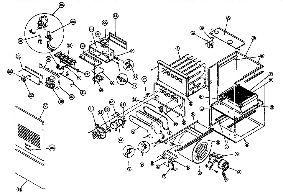
A typical parts diagram for the Armstrong Ultra SX 80 will be a detailed illustration, often an exploded view, showing all the individual components of the furnace. These diagrams usually come with a numbered key that corresponds to a parts list. This list provides the name and, sometimes, a brief description of each part.
Where to Find a Diagram: Your best bet is to consult the furnace's user manual. If you don't have the original manual, you may be able to find a digital version on the Armstrong Air website or through online HVAC parts retailers. Search using your specific furnace model number for the most accurate diagram.
Key Components of the Armstrong Ultra SX 80 Furnace
Let's break down the essential parts you'll find in the diagram, categorized by function:
1. Combustion System
This is where the magic of heating happens. It's responsible for burning the gas and creating heat.
- Gas Valve: This component controls the flow of natural gas or propane into the furnace. It's like a faucet for gas, regulated by the furnace's control board. A faulty gas valve can prevent the furnace from igniting.
- Burners: These are the devices where the gas mixes with air and ignites. They are typically made of metal and designed to distribute the flame evenly. Dirty or corroded burners can cause inefficient combustion and uneven heating.
- Igniter: The igniter is responsible for starting the combustion process. The Ultra SX 80 usually uses a hot surface igniter (HSI), which heats up to a high temperature and ignites the gas. Think of it as the furnace's "spark plug." A failing igniter is a common cause of furnace problems.
- Flame Sensor: This safety device detects the presence of a flame after the igniter has done its job. If the flame sensor doesn't detect a flame, it signals the control board to shut off the gas valve, preventing a dangerous gas buildup. A dirty flame sensor can cause the furnace to shut down prematurely.
- Combustion Chamber: This is the enclosed space where the burning of gas occurs. It's designed to withstand high temperatures.
- Heat Exchanger: The heat exchanger is a crucial component. It's a series of metal tubes or chambers that absorb the heat from the combustion process. Air from the blower motor is then passed over the heat exchanger, warming the air that's circulated throughout your home. A cracked heat exchanger is a serious safety hazard, as it can allow carbon monoxide to leak into your home. Regular inspection is vital.
2. Air Circulation System
This system moves the heated air from the furnace into your ductwork and throughout your home.
- Blower Motor: The blower motor powers the fan that circulates air through the furnace and into your home's ductwork. This is a critical component for efficient heating. Problems with the blower motor can lead to insufficient heating or overheating.
- Blower Wheel (Fan): This is the fan itself, attached to the blower motor shaft. It pulls air from the return ducts, across the heat exchanger, and then pushes the warmed air into the supply ducts.
- Blower Housing: This encloses the blower motor and wheel, directing airflow.
- Air Filter: While technically part of your ductwork, the air filter is crucial to the furnace's performance. It removes dust, pollen, and other particles from the air before it enters the furnace. A dirty air filter restricts airflow, making the furnace work harder and reducing its efficiency. It's also the simplest and most common cause of furnace problems. Replace it regularly!
3. Control and Safety System
This system monitors the furnace's operation and ensures it runs safely and efficiently.
- Control Board: The control board is the brain of the furnace. It controls all the other components, including the gas valve, igniter, blower motor, and safety devices. It receives signals from thermostats and sensors, and it regulates the furnace's operation accordingly.
- Transformer: The transformer steps down the voltage from your household electrical supply (typically 120V) to a lower voltage (typically 24V) that's used by the control board and other components.
- Thermostat: The thermostat is the user interface for controlling the furnace. It senses the temperature in your home and signals the furnace to turn on or off to maintain the desired temperature.
- Limit Switch: The limit switch is a safety device that shuts down the furnace if it gets too hot. This prevents overheating and potential damage to the furnace. A tripped limit switch can indicate a problem with airflow, a dirty air filter, or a malfunctioning blower motor.
- Rollout Switch: Another safety device, the rollout switch, detects flames that are rolling out of the combustion chamber. If this happens, it shuts down the furnace to prevent a fire hazard.
- Pressure Switch: The pressure switch monitors the pressure in the venting system. If the pressure is too low (indicating a blockage in the vent), it prevents the furnace from starting.
4. Venting System
The venting system removes the exhaust gases from the combustion process safely outside your home.
- Vent Pipe: This pipe carries the exhaust gases from the furnace to the outside. It's important that the vent pipe is properly sized and installed to ensure proper venting.
- Inducer Motor: The inducer motor helps to draw exhaust gases out of the furnace and into the vent pipe. It creates negative pressure in the combustion chamber, ensuring that the exhaust gases are properly vented.
Troubleshooting with the Parts Diagram
While you shouldn't attempt complex repairs yourself, the parts diagram can be a valuable tool for troubleshooting common furnace problems. Here are a few examples:
- Furnace won't turn on: Check the igniter, gas valve, and control board. The parts diagram can help you locate these components.
- Furnace cycles on and off frequently: This could be due to a dirty air filter, a malfunctioning limit switch, or a problem with the blower motor. Use the diagram to identify these parts.
- No heat: Check the gas valve, burners, and heat exchanger. Also, inspect the blower motor to ensure it's running.
- Unusual noises: Use the diagram to identify the location of the blower motor, inducer motor, and other moving parts. This can help you pinpoint the source of the noise.
Safety First!
Important Safety Precautions:
- Always turn off the power to the furnace at the circuit breaker before attempting any troubleshooting or repairs.
- Never work on the gas line yourself. Call a qualified gas technician for any gas-related issues.
- If you suspect a gas leak, evacuate your home immediately and call your gas company or 911.
- Carbon Monoxide: Install carbon monoxide detectors in your home and check them regularly. Carbon monoxide is a colorless, odorless gas that can be deadly.
- When in doubt, call a qualified HVAC technician. They have the expertise and tools to diagnose and repair furnace problems safely and effectively.
When to Call a Professional
While the parts diagram can be helpful, it's important to know when to call a professional HVAC technician. Here are some situations that require professional assistance:
- Cracked Heat Exchanger: This is a serious safety hazard and requires immediate attention.
- Gas Leaks: Never attempt to repair a gas leak yourself.
- Complex Electrical Issues: Problems with the control board, transformer, or other electrical components require specialized knowledge and tools.
- Refrigerant Leaks (If your furnace includes a cooling component): Think of refrigerant as the "blood" of your AC system, carrying heat from inside to outside. Leaks require specialized tools and training to repair.
- Any repair that you're not comfortable performing. It's always better to be safe than sorry.
Conclusion
Understanding the Armstrong Ultra SX 80 furnace parts diagram can be a valuable asset for homeowners. It empowers you to troubleshoot minor issues, communicate effectively with HVAC technicians, and make informed decisions about maintenance and repairs. However, always prioritize safety and call a qualified professional for complex repairs or any situation that makes you uncomfortable. By taking a proactive approach to furnace maintenance, you can ensure your home stays warm and comfortable all winter long.
Remember to consult your specific model's documentation for the most accurate parts diagram and information.