Coleman Furnace Wiring Diagram
A common headache for homeowners, especially when the weather turns, is a Coleman furnace that refuses to start. You might hear a click, a hum, or absolutely nothing at all. While there are many potential culprits, issues with the wiring are frequently to blame. Before calling a costly technician, let's explore some basic troubleshooting steps using your Coleman furnace wiring diagram.
Understanding Your Coleman Furnace Wiring Diagram
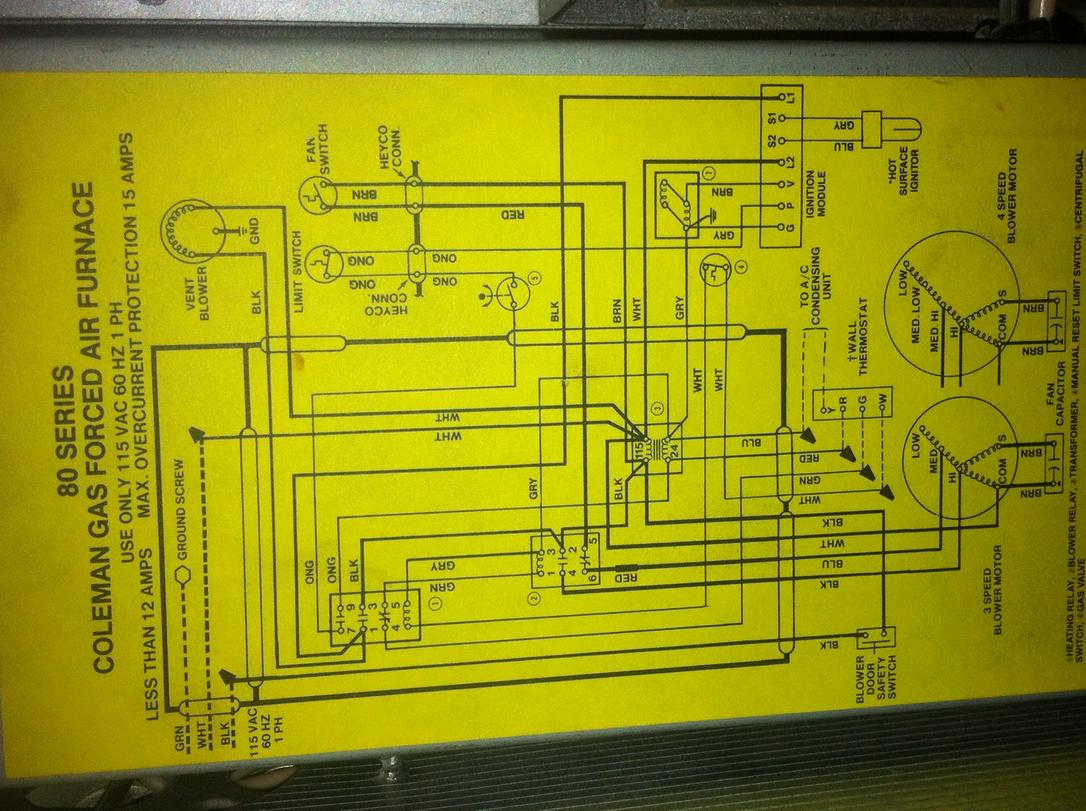
The wiring diagram is your roadmap to understanding how your furnace's electrical components interact. It's usually found inside the furnace control panel door. Don't be intimidated! While it may look complex, breaking it down makes it manageable.
Key Components to Identify on the Diagram:
- Transformer: Steps down the voltage from your household current (120V) to a lower voltage (typically 24V) used by the control circuit.
- Thermostat: Acts as the switch, signaling the furnace to turn on when heat is needed.
- Control Board: The "brains" of the operation, receiving signals from the thermostat and controlling the various components.
- Limit Switches: Safety devices that shut down the furnace if it overheats.
- Flame Sensor: Detects the presence of a flame and keeps the gas valve open.
- Gas Valve: Controls the flow of gas to the burner.
- Blower Motor: Circulates heated air throughout your home.
- Inducer Motor: Vents combustion gases safely outside.
- Wiring Connections: Shows how all these components are connected.
Important! Before you even think about touching anything, turn off the power to the furnace at the breaker box. Double-check with a non-contact voltage tester to ensure the power is indeed off.
Troubleshooting Step-by-Step
Step 1: The Obvious - Power Supply
Start with the simplest things. Is the furnace breaker switched on? Has it tripped? If it has tripped, reset it. If it trips again immediately, do not keep resetting it. This indicates a more serious electrical problem that requires a professional.
Next, check the furnace power switch, usually located on the side of the unit. Ensure it's in the "on" position.
Step 2: Thermostat Check
Is your thermostat set to "heat" and at a temperature higher than the current room temperature? It sounds basic, but it's easily overlooked. Try bumping the temperature up a few degrees to see if the furnace kicks on.
Check the thermostat batteries if it has them. A low battery can cause erratic behavior. Replace them with fresh batteries.
If you have a smart thermostat, ensure it is properly connected to your Wi-Fi network and functioning correctly. A communication issue can prevent it from signaling the furnace.
Step 3: Visual Inspection of Wiring
Now, carefully remove the furnace control panel door (after ensuring the power is OFF!). Look closely at the wiring. Are there any obvious signs of damage?
- Burned or melted wires: These indicate a short circuit or overheating.
- Loose connections: Wires should be firmly attached to their terminals.
- Corroded terminals: Corrosion can impede electrical flow.
- Rodent damage: Mice and other rodents love to chew on wires.
Using your wiring diagram, trace the wires from the transformer to the control board and from the thermostat to the control board. Pay close attention to the wire connections at the terminals.
Step 4: Tightening Connections
If you find any loose connections, carefully tighten them with a screwdriver. Make sure the screw is firmly seated but don't overtighten, as this can damage the terminal.
If you see any corroded terminals, you can try to clean them gently with a wire brush or sandpaper. Be very careful not to damage the wires or the terminals.
Step 5: Checking the Transformer Voltage
Using a multimeter (set to AC voltage), you can check the output voltage of the transformer. Refer to your wiring diagram for the expected voltage (usually 24V). Be extremely careful when working with electricity! If you are not comfortable using a multimeter, skip this step and call a professional.
Connect the multimeter probes to the transformer's output terminals. If the voltage is significantly lower than expected (or zero), the transformer may be faulty and need to be replaced. This is generally a job for a professional, as it involves working with live electricity.
Step 6: Inspecting Limit Switches
Limit switches are safety devices that shut down the furnace if it overheats. They are typically located on the furnace's heat exchanger or near the blower motor. Your wiring diagram will show their location and wiring.
Sometimes, limit switches can trip due to a temporary overheating condition. Some limit switches have a manual reset button. Look for a small button in the center of the switch. Press the button to reset the switch. If the switch trips again soon after, it indicates a more serious problem that needs professional attention (e.g., a clogged filter, a faulty blower motor).
Important: Before resetting any limit switch, try to determine the cause of the overheating. A dirty air filter is a common culprit. Replace the filter with a new one.
Step 7: Flame Sensor Check
The flame sensor is a thin metal rod located near the burner. It detects the presence of a flame and keeps the gas valve open. If the flame sensor is dirty or faulty, it can prevent the furnace from staying lit.
Turn off the gas supply to the furnace before working on the flame sensor. Locate the flame sensor and carefully remove it. Clean the sensor with fine steel wool or sandpaper. Be gentle, as the sensor is fragile.
Reinstall the flame sensor and turn the gas supply back on. See if the furnace now stays lit. If not, the flame sensor may be faulty and need to be replaced. Replacing the flame sensor is a relatively simple DIY task, but make sure to buy the correct replacement part for your furnace model.
Step 8: Control Board Inspection
The control board is the heart of your furnace, and problems here are often complex. Look for any signs of damage on the control board, such as burned components, cracked traces, or corrosion.
Some control boards have diagnostic LEDs that flash error codes. Refer to your furnace's manual or the sticker on the control panel door to interpret the error codes. These codes can help you pinpoint the problem.
Troubleshooting the control board beyond visual inspection and error code interpretation is generally best left to a professional. Control boards are complex and require specialized knowledge and equipment to diagnose and repair.
When to Call a Professional
While these DIY steps can resolve many simple wiring issues, there are times when it's essential to call a qualified HVAC technician. Here are some red flags:
- You are uncomfortable working with electricity. Safety is paramount.
- You cannot identify the components on the wiring diagram.
- The problem persists after trying the above steps.
- You suspect a gas leak. If you smell gas, immediately evacuate your home and call your gas company.
- You see significant damage to wiring or components.
- The furnace continues to trip the breaker.
- You suspect a faulty control board.
- You are dealing with the gas valve or other gas-related components. These should only be handled by a qualified professional.
Safety First!
Remember, safety is always the top priority. Always turn off the power to the furnace before working on it. Use a non-contact voltage tester to verify that the power is off. If you are unsure about any step, call a professional. Working with electricity and gas can be dangerous, and it's better to be safe than sorry.
By following these troubleshooting steps and understanding your Coleman furnace wiring diagram, you can often diagnose and fix simple wiring problems yourself, saving time and money. However, don't hesitate to call a professional when needed. A qualified technician can quickly and safely diagnose and repair more complex issues, ensuring that your furnace is running efficiently and safely for years to come.