Furnace Pressure Switch Diagram

The furnace pressure switch is a critical safety component in modern forced-air heating systems. It acts as a sentinel, ensuring that the combustion blower, also known as the induced draft fan, is operating correctly before allowing the main gas valve to open and ignite the burners. Without a properly functioning pressure switch, a furnace could vent dangerous combustion gases into the home or operate inefficiently. Understanding the furnace pressure switch diagram and its function is essential for both homeowners and HVAC professionals to ensure safe and reliable heating.
Understanding the Basics: What is a Pressure Switch?
At its core, a pressure switch is a simple device that opens or closes an electrical circuit based on a change in air pressure. In a furnace, this switch monitors the negative pressure (or vacuum) created by the induced draft fan. This negative pressure confirms that the fan is effectively drawing combustion gases out of the heat exchanger and venting them safely through the flue. The pressure switch diagram illustrates the electrical connections and pneumatic tubing that enable this crucial safety check.
Types of Pressure Switches:
Furnace pressure switches typically fall into a few categories:
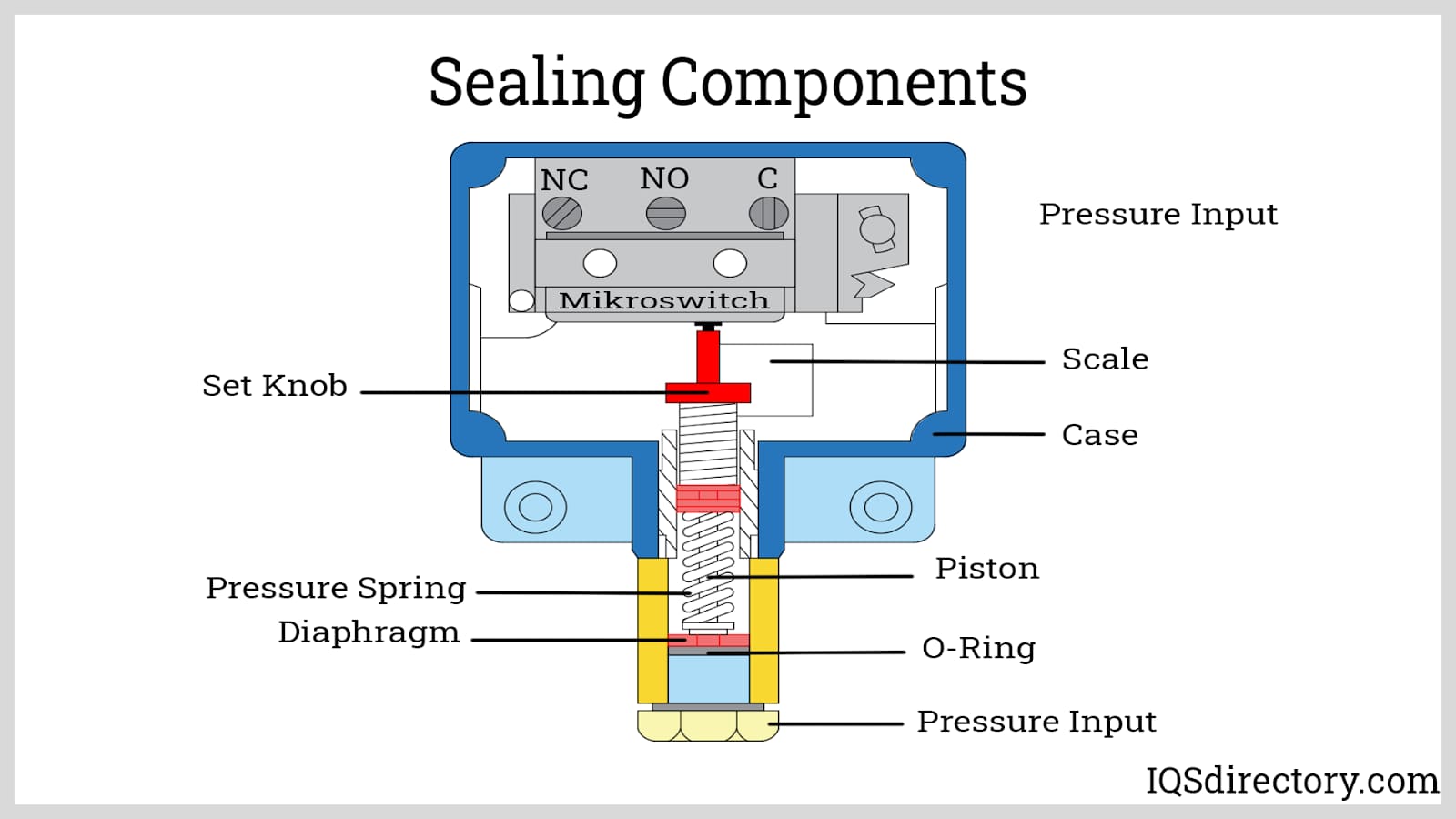
- Normally Open (NO): The electrical circuit is open until the correct negative pressure is achieved, at which point the switch closes, allowing electricity to flow. This is the most common type.
- Normally Closed (NC): The electrical circuit is closed until the correct negative pressure is achieved, at which point the switch opens, interrupting the electrical flow.
- Single-Pole Single-Throw (SPST): Has one input and one output. The switch either opens or closes a single circuit.
- Single-Pole Double-Throw (SPDT): Has one input and two outputs, allowing you to switch between two different circuits depending on the pressure.
The pressure switch diagram will indicate the type of switch being used, typically with labels such as "NO" or "NC" next to the terminals.
Decoding the Furnace Pressure Switch Diagram
A furnace pressure switch diagram is a schematic representation of how the pressure switch is integrated into the overall furnace control circuit. It shows the electrical connections, the pneumatic tubing connection, and the switch's relationship to other components like the induced draft fan motor, the control board, and the gas valve.
Key Components Depicted in the Diagram:
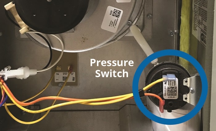
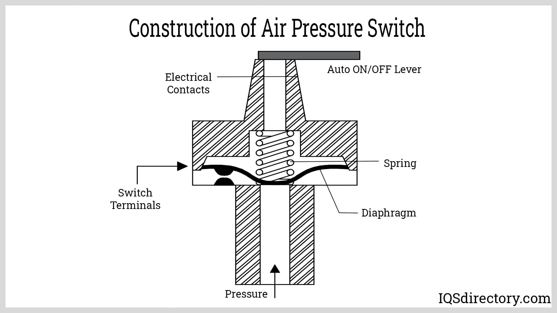
- Pressure Switch Housing: The physical body of the switch, containing the diaphragm and electrical contacts.
- Electrical Terminals: These are labeled with numbers or letters (e.g., C, NO, NC) and indicate where wires from the control board and other components should be connected.
- Pneumatic Tubing Connection: A small port where a rubber or silicone tube is attached. This tube connects to a port on the induced draft fan housing or near the flue, allowing the switch to sense the negative pressure.
- Diaphragm: An internal component that flexes in response to pressure changes, actuating the electrical contacts.
- Wiring: The diagram shows the color-coded wires and their connections between the switch and other components. This is crucial for troubleshooting and replacement.
- Control Board: The "brain" of the furnace, which monitors the pressure switch signal and controls the operation of the furnace. The diagram shows which terminals on the control board are connected to the pressure switch.
- Induced Draft Fan: While not part of the pressure switch itself, the diagram often shows the induced draft fan and its relationship to the pressure switch, highlighting the path of the pneumatic tubing.
Reading the Diagram: A Step-by-Step Guide
- Identify the Pressure Switch: Locate the symbol representing the pressure switch. It usually looks like a switch with a circle or square representing the housing.
- Trace the Wiring: Follow the lines representing the wires from the pressure switch terminals to the control board and other components. Note the wire colors and terminal designations.
- Locate the Pneumatic Tubing: Identify the connection point for the pneumatic tubing and trace its path back to the induced draft fan.
- Understand the Logic: Determine whether the switch is normally open or normally closed. Understand how the change in pressure affects the electrical circuit. For example, if it's a normally open switch, the diagram will show the circuit being open until sufficient negative pressure closes the switch.
- Refer to the Legend: Most diagrams have a legend that explains the symbols and abbreviations used.
Troubleshooting Pressure Switch Problems
A malfunctioning pressure switch can cause a variety of problems, including the furnace failing to ignite, short cycling, or displaying error codes. Here are some common issues and how to troubleshoot them, often referencing the pressure switch diagram:
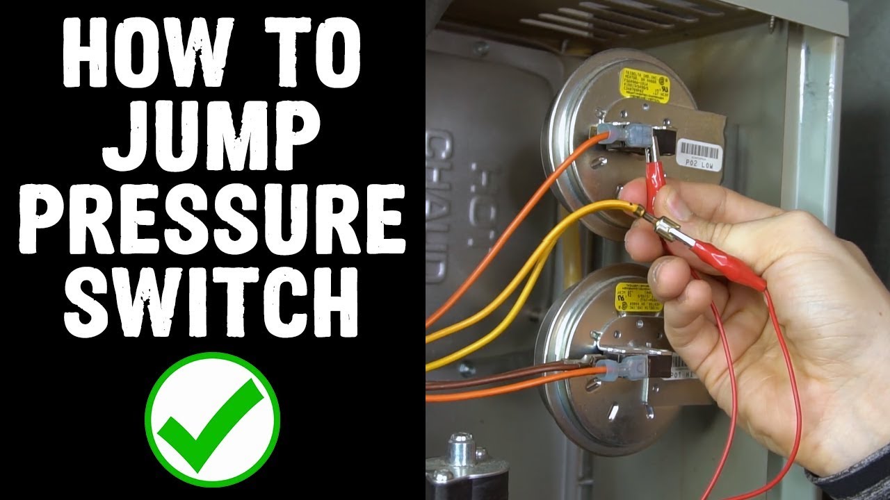
- Faulty Switch: The switch itself may be defective and not responding to pressure changes. Use a multimeter to test the continuity of the switch in both the "at rest" and "activated" states. The pressure switch diagram will show which terminals to test.
- Clogged Tubing: The pneumatic tubing can become clogged with debris, preventing the switch from sensing the pressure. Disconnect the tubing and blow it out to clear any obstructions. Inspect the ports on the induced draft fan and the pressure switch for blockages.
- Cracked or Leaking Tubing: Cracks or leaks in the tubing can prevent the switch from sensing the correct pressure. Replace the tubing if necessary.
- Weak Induced Draft Fan: If the induced draft fan is not generating enough negative pressure, the switch will not activate. Check the fan motor and impeller for damage or wear. Compare the measured pressure with the specifications listed on the furnace.
- Blocked Flue: A blocked flue can prevent the induced draft fan from creating sufficient negative pressure. Inspect the flue for obstructions.
- Wiring Issues: Loose or corroded wiring connections can prevent the switch from functioning correctly. Check the wiring connections at the switch, the control board, and other components. The pressure switch diagram will be invaluable in tracing the wiring.
Safety Note: Always disconnect power to the furnace before troubleshooting electrical components. If you are not comfortable working with electricity or gas, consult a qualified HVAC technician.
Replacing a Pressure Switch
If the pressure switch is determined to be faulty, it will need to be replaced. Here's a general procedure:
- Turn Off Power: Disconnect the power to the furnace at the breaker.
- Locate the Switch: The pressure switch is typically located near the induced draft fan.
- Disconnect Wiring: Carefully disconnect the wires from the switch terminals, noting their positions (or taking a picture) for correct reassembly. Refer to the pressure switch diagram.
- Disconnect Tubing: Disconnect the pneumatic tubing from the switch.
- Remove the Switch: Remove the screws or clips holding the switch in place and remove the old switch.
- Install the New Switch: Install the new switch in the same location, securing it with the screws or clips.
- Reconnect Tubing: Reconnect the pneumatic tubing to the switch.
- Reconnect Wiring: Reconnect the wires to the correct terminals, using the notes or picture you took earlier, referencing the pressure switch diagram.
- Restore Power: Restore power to the furnace.
- Test the Furnace: Turn on the furnace and observe its operation to ensure that the new switch is functioning correctly.
Cost and Lifespan
The cost of a pressure switch typically ranges from $20 to $80, depending on the make and model of the furnace. The cost of labor for a professional HVAC technician to replace the switch can range from $100 to $300 or more, depending on the complexity of the job and the location. A pressure switch typically lasts for 5 to 15 years, but its lifespan can be affected by factors such as the operating environment and the quality of the switch.
Conclusion
The furnace pressure switch is a vital safety component that protects homeowners from dangerous combustion gases and ensures efficient furnace operation. Understanding the pressure switch diagram is crucial for troubleshooting and maintaining your furnace. While some basic troubleshooting can be done by homeowners, any complex repairs or replacements should be performed by a qualified HVAC technician. Regular furnace maintenance, including inspecting the pressure switch and its tubing, can help prevent problems and extend the life of your heating system.