Herm 3 Wire Ac Dual Capacitor Wiring Diagram
Understanding the intricacies of HVAC (Heating, Ventilation, and Air Conditioning) systems is crucial for homeowners, HVAC technicians, and facility managers alike. Among the numerous components that make up these systems, the dual capacitor plays a pivotal role, particularly in single-phase air conditioning units and heat pumps. This article delves into the Herm 3 Wire AC Dual Capacitor Wiring Diagram, breaking down its function, wiring configurations, troubleshooting tips, and best practices.
The Role of a Dual Capacitor in HVAC Systems
A dual capacitor is essentially two capacitors housed in a single cylindrical casing. These capacitors provide the necessary electrical boost to start and run the compressor motor and the fan motor. Instead of using two separate capacitors, a dual capacitor offers a more compact and cost-effective solution. It's essential in providing the initial torque to overcome inertia and ensure smooth motor operation. Without a functioning capacitor, your air conditioner might struggle to start, leading to inefficiency and potential motor damage.
Capacitor Terminals Explained
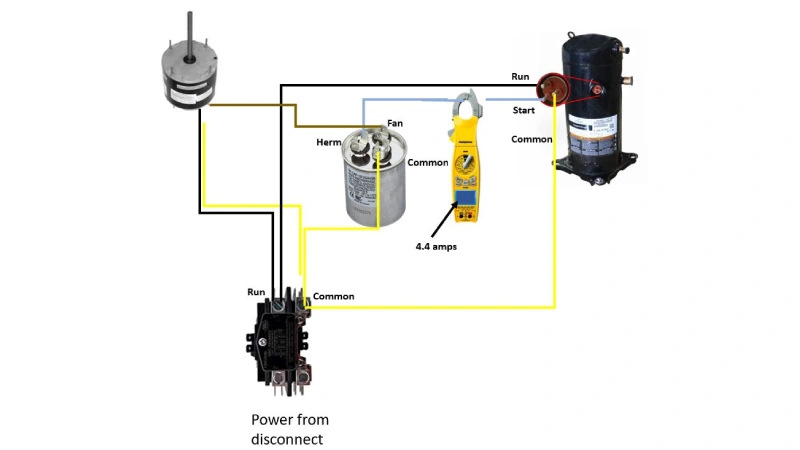
The Herm 3 Wire AC Dual Capacitor Wiring Diagram revolves around understanding the capacitor's terminals. Typically, you'll find three terminals, each labeled with a specific function:
- C (Common): This terminal serves as the common connection point for both the compressor and fan circuits. It's usually connected to the power supply neutral wire.
- H or HERM (Hermetically Sealed Compressor): This terminal connects to the starting winding of the compressor motor. This leg of the capacitor delivers the necessary phase shift to kickstart the compressor.
- F or FAN: This terminal connects to the fan motor. It provides the capacitance needed for the fan motor to run efficiently.
Understanding these terminals is fundamental to interpreting and working with the wiring diagram.
Deciphering the Herm 3 Wire AC Dual Capacitor Wiring Diagram
A typical Herm 3 Wire AC Dual Capacitor Wiring Diagram illustrates how these three terminals integrate into the broader HVAC electrical system. While specific diagrams may vary depending on the manufacturer and unit model, the core principles remain consistent.
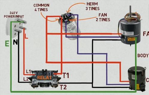
- Power Supply: The diagram usually begins with the power supply, typically 220-240V AC for residential units. One leg of the power supply (usually the hot wire) connects to the contactor.
- Contactor: The contactor acts as an electrically controlled switch, allowing power to flow to the compressor and fan motors when the thermostat calls for cooling.
- Compressor Circuit: From the contactor, the hot wire leads to the compressor motor windings and the H (HERM) terminal of the dual capacitor. The C (Common) terminal of the capacitor connects to the neutral wire. The compressor motor also has a common terminal that connects directly to the neutral wire.
- Fan Circuit: Similarly, the hot wire from the contactor also connects to the fan motor windings and the F (FAN) terminal of the dual capacitor. The C (Common) terminal again connects to the neutral wire. The fan motor also has a common terminal that connects directly to the neutral wire.
- Grounding: A crucial safety element, the grounding wire connects to the chassis of the unit, providing a path for electrical faults to prevent shocks.
It's crucial to remember that safety is paramount when working with electrical systems. Always disconnect the power supply before inspecting or modifying any wiring. Use a multimeter to verify that the power is indeed off.
Reading Capacitor Markings
Dual capacitors are marked with two capacitance values, usually expressed in microfarads (µF) or MFD. These values correspond to the HERM and FAN terminals. For example, a capacitor might be labeled "45+5 µF," indicating 45 µF for the compressor (HERM) and 5 µF for the fan. It’s vital to replace a capacitor with one that has the same or very closely matching capacitance values to ensure proper motor operation and prevent damage. Voltage ratings are also crucial; the replacement capacitor must have a voltage rating equal to or greater than the original.
Troubleshooting Dual Capacitor Issues
A malfunctioning dual capacitor can manifest in various ways, impacting the performance of your HVAC system. Common symptoms include:
- Hard Starting: The compressor or fan struggles to start or makes a humming noise without running.
- Reduced Cooling: Insufficient cooling capacity due to the compressor not running at full speed.
- Overheating: The compressor or fan motor overheating due to inefficient operation.
- Tripped Breakers: The system tripping circuit breakers due to the motor drawing excessive current during startup.
- Complete Failure: The compressor or fan simply not running at all.
Testing a Dual Capacitor:
- Safety First: Disconnect the power supply to the HVAC unit.
- Discharge the Capacitor: Use a discharge tool (a resistor) to safely discharge the capacitor. Capacitors can store a dangerous electrical charge even when disconnected.
- Visual Inspection: Look for signs of physical damage, such as bulging, leaking, or corrosion.
- Multimeter Test: Use a multimeter with a capacitance setting to measure the capacitance values between the C terminal and the HERM and FAN terminals. Compare these readings to the capacitor's labeled values. A significant deviation (e.g., more than 10% off) indicates a faulty capacitor.
If the capacitor tests bad, it needs replacement. It's highly recommended to hire a qualified HVAC technician for this task, especially if you're not comfortable working with electrical systems. Incorrect wiring can damage the system or pose a safety hazard.
Choosing the Right Replacement Capacitor
When replacing a dual capacitor, several factors must be considered:
- Capacitance Value: Match the capacitance values (µF or MFD) as closely as possible to the original capacitor. Using a capacitor with significantly different values can damage the motor.
- Voltage Rating: The voltage rating of the replacement capacitor must be equal to or greater than the original. A lower voltage rating could lead to premature failure.
- Physical Size: Ensure the replacement capacitor fits within the available space in the unit.
- Operating Temperature: Select a capacitor rated for the operating temperatures expected in the HVAC unit.
Opting for a reputable brand and a capacitor specifically designed for HVAC applications is also a good practice. These capacitors are built to withstand the harsh conditions and frequent start/stop cycles common in HVAC systems.
Preventive Maintenance and Best Practices
Regular maintenance can extend the lifespan of your dual capacitor and prevent unexpected breakdowns. Here are some best practices:
- Regular Inspection: Visually inspect the capacitor for signs of damage during routine HVAC maintenance.
- Cleaning: Keep the area around the capacitor clean and free of debris to prevent overheating.
- Professional Checkups: Schedule annual HVAC checkups with a qualified technician. They can test the capacitor and identify potential issues before they escalate.
- Avoid Overloading: Ensure the HVAC system is appropriately sized for the space it's cooling or heating. Overloading the system can put extra strain on the capacitor and other components.
Dual Capacitor Wiring Configurations: Beyond the Basics
While the Herm 3 Wire AC Dual Capacitor Wiring Diagram is the most common configuration, variations exist depending on the complexity and design of the HVAC system. Some systems might use additional relays or control circuits, which can alter the wiring scheme slightly. Consulting the manufacturer's wiring diagram for your specific unit is always the best approach.
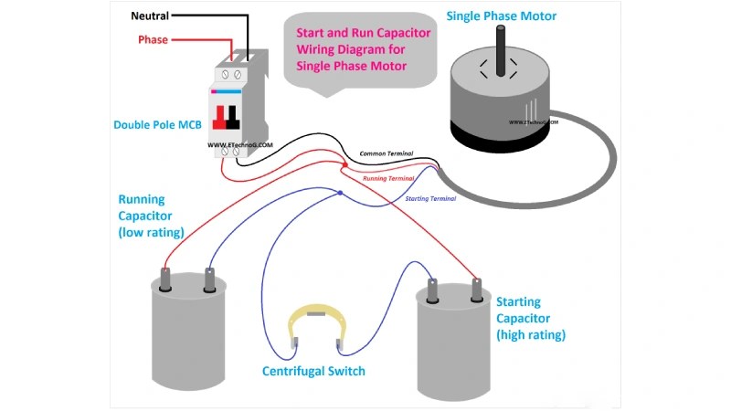
Single vs. Dual Capacitors: A Quick Comparison
While this article focuses on dual capacitors, it's worth briefly comparing them to single capacitors. Single capacitors are used in simpler applications, where only one motor (either the compressor or the fan) requires a starting boost. Dual capacitors offer a more integrated and cost-effective solution when both motors need capacitance. Choosing between single and dual capacitors depends on the specific requirements of the HVAC system.
Cost, Efficiency, and Lifespan Considerations
The cost of a dual capacitor typically ranges from $20 to $100, depending on the capacitance values, voltage rating, and brand. The labor cost for replacement can vary depending on the complexity of the job and the technician's hourly rate. A properly maintained dual capacitor should last for several years, typically between 5 to 10 years, depending on usage and environmental conditions.
An efficient capacitor contributes to the overall efficiency of the HVAC system. A failing capacitor can cause the motor to draw more current, leading to higher energy consumption. Replacing a worn-out capacitor can often improve the system's efficiency and reduce energy bills. Remember, ignoring a failing capacitor can lead to more expensive repairs down the line, such as compressor motor damage.
In conclusion, understanding the Herm 3 Wire AC Dual Capacitor Wiring Diagram is crucial for anyone involved in maintaining or repairing HVAC systems. By grasping the function of the capacitor, interpreting the wiring diagram, and following best practices for troubleshooting and maintenance, you can ensure the reliable and efficient operation of your air conditioning system.