How To Know Which Orifice To Use
Choosing the correct orifice, also known as a metering device, is crucial for optimal performance in various systems, especially in refrigeration and air conditioning (AC). The orifice regulates the flow of fluids, ensuring the system operates efficiently and effectively. Using the wrong orifice can lead to poor performance, system damage, and wasted energy. This guide will provide you with the knowledge to understand orifices and select the appropriate one for your specific application.
Understanding the Role of an Orifice
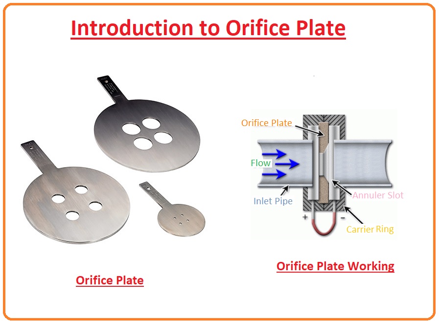
An orifice is essentially a precisely sized restriction in a fluid line. Its primary function is to create a pressure drop, which controls the flow rate of the fluid passing through it. The size of the orifice directly impacts the amount of fluid that can flow in a given period.
Think of it like this: imagine a garden hose with a nozzle. The nozzle is similar to an orifice. When the nozzle is wide open, water flows freely. When you partially close the nozzle, the water flow is restricted, creating pressure and a more focused stream. An orifice works in a similar way, but with far more precision and control.
Why is the Correct Orifice Size Important?
Using the correct orifice size is vital for several reasons:
- Optimal Performance: The right orifice ensures the system operates at its designed capacity.
- Efficiency: Proper flow control maximizes energy efficiency, reducing operating costs.
- System Protection: Correctly sized orifices prevent excessive pressure or flow rates that can damage components.
- Temperature Control: In refrigeration and AC systems, the orifice plays a key role in maintaining desired temperatures.
Factors Influencing Orifice Selection
Selecting the appropriate orifice involves considering several factors specific to the system in which it will be used. These factors determine the required flow rate and pressure drop.
1. System Type and Application
The type of system dictates the operating parameters and fluid requirements. Consider the following:
- Refrigeration Systems: Used in refrigerators, freezers, and other cooling applications.
- Air Conditioning Systems: Found in homes, offices, and vehicles for cooling and dehumidifying air.
- Hydraulic Systems: Utilized in machinery and equipment for power transmission and control.
- Pneumatic Systems: Employed in automation and control systems using compressed air.
2. Fluid Type and Properties
The fluid being controlled significantly impacts the orifice selection. Key properties to consider include:
- Viscosity: A measure of a fluid's resistance to flow. Highly viscous fluids require larger orifices.
- Density: The mass per unit volume of the fluid. Denser fluids require different orifice sizing compared to less dense fluids.
- Specific Gravity: The ratio of a fluid's density to the density of water.
- Refrigerant Type (for AC/Refrigeration): Different refrigerants have different thermodynamic properties, affecting the required orifice size. Think of refrigerant as the 'blood' of your AC system, carrying heat from inside to outside. Using the wrong refrigerant will require a different sized orifice.
3. Flow Rate Requirements
The required flow rate is a critical factor. It represents the volume of fluid that needs to pass through the orifice in a given time period. The flow rate is determined by the system's cooling or heating load, or the power requirements of the equipment.
To determine the flow rate, you'll need to consult the system's specifications or perform calculations based on its operating parameters.
4. Pressure Drop
The pressure drop is the difference in pressure between the inlet and outlet of the orifice. It's a crucial factor in determining the flow rate. A higher pressure drop generally results in a higher flow rate for a given orifice size, but it also requires more energy to pump the fluid.
The desired pressure drop is determined by the system's design and the performance requirements. It needs to be balanced with the energy efficiency of the system.
5. Operating Temperature and Pressure
The temperature and pressure at which the system operates significantly impact the fluid's properties and the orifice's performance. High temperatures can reduce fluid viscosity, while high pressures can increase density. These changes need to be accounted for when selecting the orifice.
6. System Capacity
The capacity of the system, often measured in BTU/hr (British Thermal Units per hour) for AC/Refrigeration, directly relates to the amount of heat the system needs to remove or add. A higher capacity system will generally require a larger orifice to accommodate the increased refrigerant flow. Consult the manufacturer's specifications for the appropriate orifice size based on the system's capacity.
Methods for Determining Orifice Size
Several methods can be used to determine the correct orifice size. The most common approaches include:
1. Manufacturer's Specifications
The most reliable method is to consult the manufacturer's specifications for the specific system. Manufacturers provide detailed information on the recommended orifice size based on the system's operating parameters and fluid type. This information is typically found in the system's manual or technical documentation.
2. Flow Rate Calculations
If manufacturer specifications are unavailable, you can calculate the required orifice size based on the desired flow rate, pressure drop, and fluid properties. This involves using fluid dynamics equations, such as the orifice equation.
The orifice equation relates the flow rate to the orifice size, pressure drop, and fluid properties. While the equation itself can be complex, there are online calculators and software tools that can simplify the calculations.
Here's a simplified version of the principle:
Flow Rate = (Orifice Area) x (Discharge Coefficient) x Square Root (2 x Pressure Drop / Fluid Density)
Where:
- Flow Rate: The volume of fluid passing through the orifice per unit time.
- Orifice Area: The cross-sectional area of the orifice opening.
- Discharge Coefficient: A dimensionless value that accounts for the non-ideal flow characteristics of the orifice (typically between 0.6 and 0.8).
- Pressure Drop: The difference in pressure between the inlet and outlet of the orifice.
- Fluid Density: The mass per unit volume of the fluid.
Solving this equation for Orifice Area allows you to determine the required orifice size.
3. Charts and Tables
Many industries have standardized charts and tables that provide recommended orifice sizes based on system parameters. These charts are typically specific to the application and fluid type.
For example, in the HVAC industry, there are charts that list recommended orifice sizes for different refrigerants and system capacities.
4. Experience and Expertise
Experienced technicians often develop a good understanding of orifice sizing based on their practical knowledge. They can often estimate the correct orifice size based on the system's behavior and performance. However, this method should be used with caution and should always be verified with calculations or manufacturer specifications whenever possible.
Practical Considerations
Besides the theoretical calculations, several practical considerations can influence the final orifice selection:
1. Available Orifice Sizes
Orifices are typically available in standardized sizes. You may need to select the closest available size that meets the calculated requirements. It's better to err on the side of a slightly smaller orifice than a significantly larger one, as an undersized orifice can be easily adjusted, while an oversized orifice is more difficult to correct.
2. Adjustable Orifices
In some applications, adjustable orifices are used. These orifices allow you to fine-tune the flow rate after installation. Adjustable orifices are particularly useful in systems where the operating conditions may vary or are not precisely known.
3. Orifice Material
The material of the orifice should be compatible with the fluid being controlled and the operating environment. Common orifice materials include brass, stainless steel, and plastic. Stainless steel is often preferred for its corrosion resistance and durability.
4. Orifice Shape
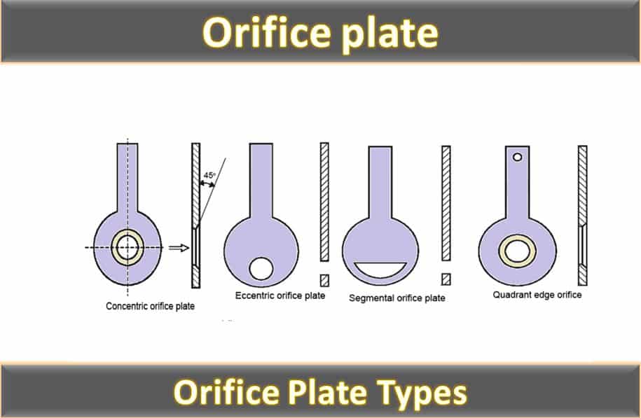
The shape of the orifice can also impact its performance. Sharp-edged orifices are commonly used for accurate flow measurement, while rounded orifices provide smoother flow and reduce turbulence. The choice of orifice shape depends on the specific application requirements.
Troubleshooting Orifice Problems
Once the orifice is installed, it's essential to monitor the system's performance and troubleshoot any potential problems. Common orifice-related issues include:
1. Clogging
Orifices can become clogged with debris or contaminants in the fluid. This reduces the flow rate and can lead to system malfunctions. Regular maintenance and filtration can help prevent clogging.
2. Erosion
Over time, the orifice can erode due to the abrasive nature of the fluid. This increases the orifice size and can lead to excessive flow rates. Regular inspection and replacement of worn orifices are necessary.
3. Incorrect Orifice Size
If the system is not performing as expected, the orifice size may be incorrect. Double-check the calculations and specifications to ensure the correct orifice size is installed.
Summary
Selecting the correct orifice is a critical step in designing and maintaining fluid control systems. By carefully considering the system type, fluid properties, flow rate requirements, pressure drop, and operating conditions, you can choose the appropriate orifice size to ensure optimal performance, efficiency, and reliability. Always consult manufacturer specifications whenever possible, and consider seeking expert advice when dealing with complex systems.
Remember that understanding the fundamentals and taking a systematic approach will greatly increase your chances of success in selecting the right orifice for your application.