How To Read A Pump Curve
Imagine this: you're enjoying a hot shower, and suddenly, the water pressure drops to a trickle. Or maybe your sprinkler system is sputtering instead of providing consistent coverage. Chances are, the pump responsible for maintaining that water pressure isn't performing as it should. Understanding how to read a pump curve is crucial for diagnosing such problems and ensuring your pump is operating efficiently.
What is a Pump Curve and Why Should I Care?
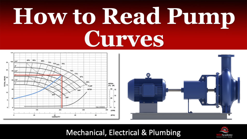
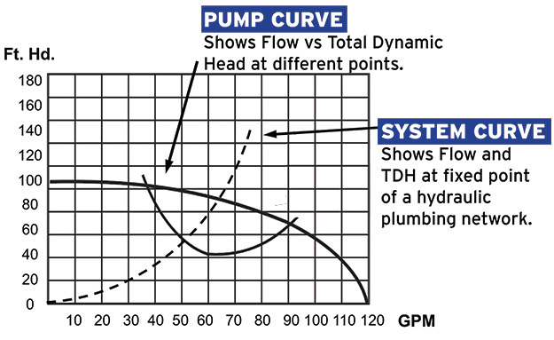
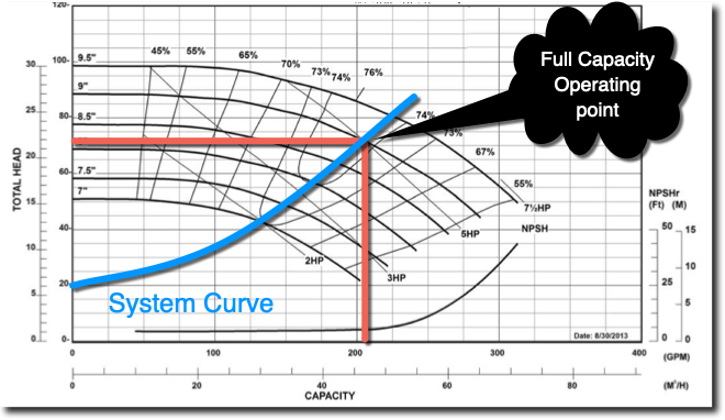
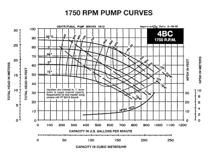
A pump curve, also known as a performance curve, is a graphical representation of a pump's capabilities. It shows the relationship between flow rate (the amount of liquid the pump moves per unit of time, often measured in gallons per minute or GPM) and total dynamic head (TDH, which is the total pressure or resistance the pump has to overcome, usually measured in feet or meters). Think of it as the pump's performance resume.
Understanding this curve is essential for:
- Selecting the right pump: Ensuring the pump meets the specific needs of your application.
- Troubleshooting performance issues: Diagnosing why your pump isn't delivering the expected flow or pressure.
- Optimizing pump efficiency: Identifying the operating point that maximizes the pump's performance and minimizes energy consumption.
Breaking Down the Pump Curve
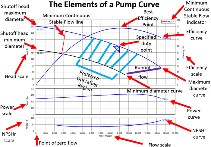
Let's dissect a typical pump curve. You'll usually find the following elements:
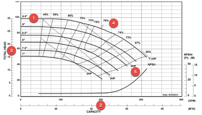
- X-Axis (Horizontal): Represents the flow rate, usually in GPM. As you move to the right on the x-axis, the flow rate increases.
- Y-Axis (Vertical): Represents the total dynamic head (TDH), usually in feet. As you move up the y-axis, the head increases.
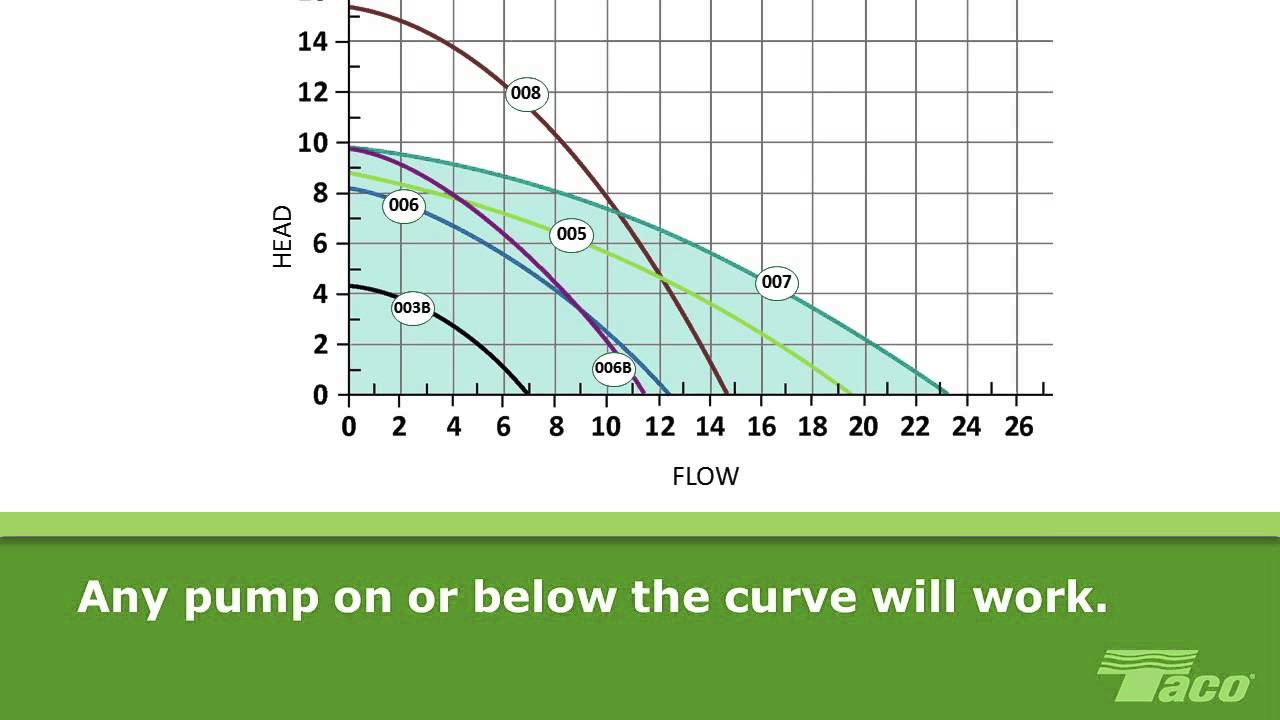
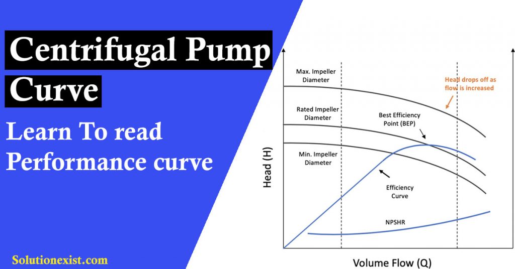
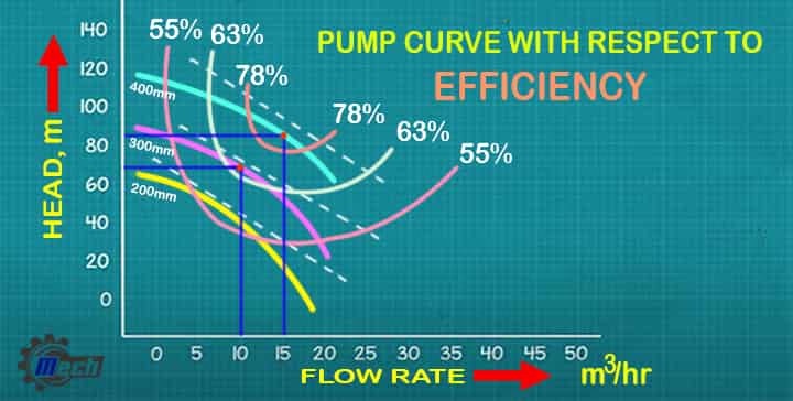
- Curve(s): The main curve, or curves, show the relationship between flow rate and head. Different curves might represent different impeller sizes or pump speeds.
- Pump Model Information: The pump model number will allow you to find the correct pump curve from the manufacturer.
- Efficiency Curves: These curves show the pump's efficiency at different operating points. They are often represented as lines or shaded areas. These are important when selecting a pump to minimize energy consumption.
- Power Curve: This shows the power (usually in horsepower or kilowatts) required to operate the pump at different flow rates and heads. It helps to ensure the motor is appropriately sized.
- NPSH Required Curve: Net Positive Suction Head Required (NPSHR) is the minimum pressure required at the pump's suction inlet to prevent cavitation. This curve is crucial to avoid damage to the pump.
Reading the Curve:
To determine the pump's head at a given flow rate, find the desired flow rate on the x-axis, move vertically up to the pump curve, and then move horizontally left to read the corresponding head on the y-axis. Conversely, to determine the flow rate at a given head, find the desired head on the y-axis, move horizontally right to the pump curve, and then move vertically down to read the corresponding flow rate on the x-axis.
Step-by-Step Guide to Troubleshooting with a Pump Curve
Let's use a common scenario: your well pump is providing weak water pressure to your house.
Step 1: Gather Information
Before diving into the pump curve, gather as much information as possible:
- Pump Model Number: This is crucial for finding the correct pump curve. Look for a sticker or plate on the pump housing.
- Current Flow Rate: Measure the actual flow rate at a faucet or sprinkler head. You can use a flow meter or simply time how long it takes to fill a known volume container (e.g., a 5-gallon bucket).
- Pressure at the Pump: Use a pressure gauge to measure the pressure at the pump outlet.
- Static Water Level (for Well Pumps): Measure the distance from the top of the well casing to the water level when the pump is *not* running. This requires specialized tools and is best left to professionals. However, knowing this helps determine the total dynamic head.
- Piping System Details: Note the length, diameter, and type of pipes, as well as the number and type of fittings (elbows, tees, valves). This information is necessary to calculate friction losses in the system.
Step 2: Find the Pump Curve
Once you have the pump model number, you can usually find the pump curve online on the manufacturer's website or in the pump's manual. If you can't find it online, contact the pump manufacturer or a local pump supplier.
Step 3: Calculate Total Dynamic Head (TDH)
TDH is the total pressure the pump needs to overcome. It's calculated as follows:
TDH = Static Head + Pressure Head + Friction Head
- Static Head: The vertical distance the pump has to lift the water. For a well pump, it's the distance from the water level in the well (after drawdown) to the highest point of use in your house. For a booster pump, it's the difference in elevation between the pump inlet and outlet.
- Pressure Head: The desired pressure at the outlet, converted to feet of head. Use the conversion: 1 PSI = 2.31 feet of head. If you want 60 PSI at your faucet, that's 60 PSI * 2.31 ft/PSI = 138.6 feet of head.
- Friction Head: The pressure loss due to friction in the pipes and fittings. This is more complex to calculate and depends on the pipe material, diameter, length, and flow rate. There are online calculators and tables available to estimate friction loss. Alternatively, a professional can accurately measure it.
Important Note: Accurately calculating friction head requires some knowledge of fluid dynamics and piping systems. If you're unsure, consult a professional plumber or pump technician.
Step 4: Plot Your Operating Point on the Pump Curve
Now that you have the actual flow rate and the calculated TDH, you can plot your operating point on the pump curve. Find the flow rate on the x-axis and the TDH on the y-axis, and mark the intersection. This point represents how your pump is currently performing.
Step 5: Analyze the Results
Compare your operating point to the pump curve. Here's what different scenarios might indicate:
- Operating Point Below the Curve: This indicates the pump is not performing as expected. Possible causes include:
- Clogged Impeller: Debris blocking the impeller reduces flow and pressure.
- Worn Impeller: Over time, the impeller can wear down, reducing its efficiency.
- Air Leak in the Suction Line (for Well Pumps): Air entering the pump reduces its ability to create suction.
- Incorrect Voltage: Check the voltage at the pump motor. Low voltage can significantly reduce performance.
- Partially Closed Valve: A valve restricting flow in the system.
- High Static Water Level Drawdown: Excessive drawdown in the well reduces the pump's suction head.
- Operating Point Far to the Right on the Curve (High Flow, Low Head): This might indicate a broken or leaking pipe in the system. The pump is moving a lot of water, but the pressure is low because it's escaping somewhere.
- Operating Point Close to the End of the Curve (Low Flow, High Head): This could mean the pump is struggling to overcome a very high resistance. This could be due to a clogged pipe, a closed valve, or an undersized pump for the application.
Step 6: Basic Troubleshooting and DIY Fixes (Use Caution!)
Important Safety Note: Before attempting any repairs, always disconnect the power to the pump at the circuit breaker. When working with electricity, water, or mechanical components, exercise extreme caution to avoid injury. If you are uncomfortable with any of these steps, consult a qualified professional.
- Check the Power Supply:
- Use a multimeter to verify the voltage at the pump motor. It should match the voltage specified on the pump's nameplate.
- Check the circuit breaker to ensure it's not tripped. If it trips repeatedly, there may be an electrical problem that requires professional attention.
- Inspect the wiring for any signs of damage or corrosion. Replace any damaged wiring.
- Inspect for Air Leaks (for Well Pumps):
- Check all fittings on the suction line for tightness.
- Look for cracks or holes in the suction pipe.
- Consider having a professional conduct a well inspection to check for casing leaks or other issues.
- Check for Clogs:
- Examine the pump inlet and outlet for any debris or obstructions.
- If possible, carefully remove the pump impeller and clean it of any debris. Note: This may require specialized tools and knowledge.
- Flush the pipes in the system to remove any sediment or buildup.
- Verify Valve Positions:
- Ensure all valves in the system are fully open. Partially closed valves can significantly restrict flow.
- Capacitor Testing (For Some Pumps): Single phase pump motors use capacitors to start and run. A faulty capacitor can prevent the pump from starting or reduce its performance. Testing capacitors requires knowledge of electrical circuits and should be performed by a qualified technician.
Step 7: When to Call a Professional
Some problems require professional expertise and equipment. Always call a qualified plumber or pump technician if:
- You are uncomfortable working with electricity, water, or mechanical components.
- You suspect a major component failure, such as a damaged impeller, motor, or pump housing.
- You are dealing with a well pump issue that involves accessing the well itself (measuring static water level after drawdown requires specialized tools).
- You are unsure how to properly diagnose the problem.
- The pump is still under warranty. Attempting repairs yourself may void the warranty.
- There is any suspicion of gas leaks, backflow or other serious plumbing concerns.
Understanding Variable Frequency Drives (VFDs) and Pump Curves
Many modern pumps are equipped with Variable Frequency Drives (VFDs). A VFD allows you to control the pump's motor speed, which directly affects the pump's performance.
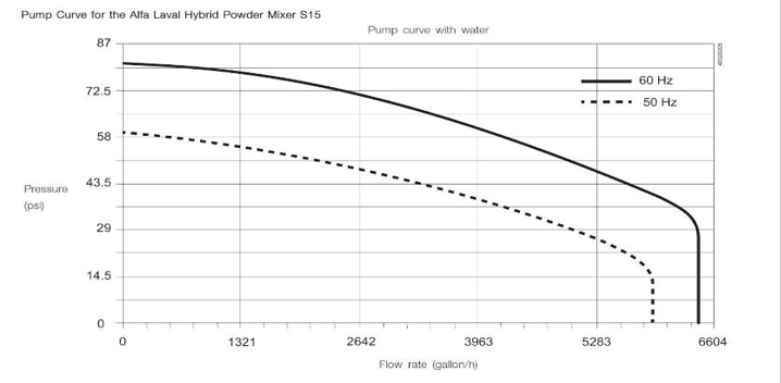
When a pump is running with a VFD, the pump curve changes depending on the motor speed (frequency). The manufacturer's data sheet will have a family of curves which show how the pump's performance changes at various speeds.
Troubleshooting pumps with VFDs requires additional considerations:
- VFD Settings: Check the VFD settings to ensure they are appropriate for the application. Incorrect settings can cause the pump to operate inefficiently or even damage the pump.
- VFD Fault Codes: If the VFD displays a fault code, consult the VFD's manual to determine the cause of the fault and how to resolve it.
- Motor Speed: Monitor the motor speed to ensure it is within the specified range.
Working with VFDs requires specialized knowledge and should be left to qualified professionals.
Conclusion
Reading a pump curve might seem daunting at first, but with a little understanding and careful observation, it can be a valuable tool for troubleshooting and optimizing your pump's performance. By following these steps and exercising caution, you can diagnose common problems and potentially save yourself the cost of a service call. Remember to prioritize safety and consult a professional when necessary.