Low Voltage Wiring Diagram For Air Conditioner

Frequently Asked Questions: Low Voltage Wiring Diagrams for Air Conditioners
Understanding the low voltage wiring in your air conditioning system is crucial for troubleshooting, maintenance, and ensuring optimal performance. This FAQ aims to answer common questions homeowners and facility managers have about these diagrams.
Q: What exactly is a low voltage wiring diagram for an air conditioner, and why is it important?
A low voltage wiring diagram for an air conditioner is a schematic representation of the control circuitry that governs the operation of your AC unit. Think of it as a roadmap for the electrical components and their connections within the system, but focusing specifically on the lower voltage circuits (typically 24V AC) responsible for things like thermostat communication, safety switches, and relay control.
It's important for several reasons:
- Troubleshooting: It helps technicians quickly identify faulty components or wiring problems when the AC isn't working correctly. Without it, tracing wires and understanding the circuit flow can be incredibly time-consuming and lead to misdiagnosis.
- Maintenance: It provides a reference for checking wiring connections and ensuring they are secure during routine maintenance.
- Repair: It guides the replacement of components like thermostats, relays, and transformers. Knowing where each wire goes is essential for a successful repair.
- Understanding System Operation: Even for non-technicians, studying the diagram can provide a basic understanding of how the air conditioner's control system works.
- Safety: Ensures correct and safe electrical connections are made, preventing potential hazards.
Q: Where can I find the low voltage wiring diagram for my specific air conditioner model?
The most common locations for finding the low voltage wiring diagram are:
- Inside the Unit's Control Panel: Many AC units have the wiring diagram printed on a sticker or folded sheet of paper and attached to the inside of the control panel cover. This is usually the first place to look.
- Attached to the Unit Housing: Sometimes, the diagram is affixed to an external panel or the main unit housing itself.
- In the Installation Manual: The installation manual that came with the air conditioner should contain the wiring diagram. Keep your installation manuals!
- Manufacturer's Website: Most major air conditioner manufacturers have a website where you can download manuals and technical documents for their products. You'll typically need the model number of your unit.
- Online HVAC Forums and Databases: Some online communities and databases dedicated to HVAC systems may have wiring diagrams shared by other users. However, always verify the accuracy of these diagrams against other sources.
Important Safety Note: When accessing the control panel to locate the diagram, always turn off the power to the air conditioner at the circuit breaker to avoid electrical shock.
Q: What are the key components typically shown in a low voltage wiring diagram for an air conditioner?
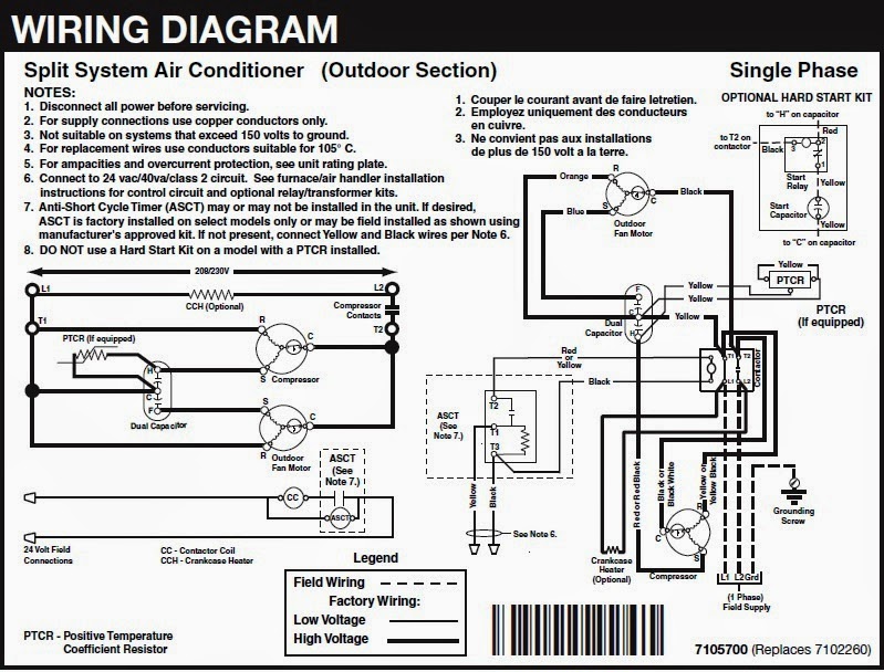
A typical low voltage wiring diagram will depict the following components and their connections:
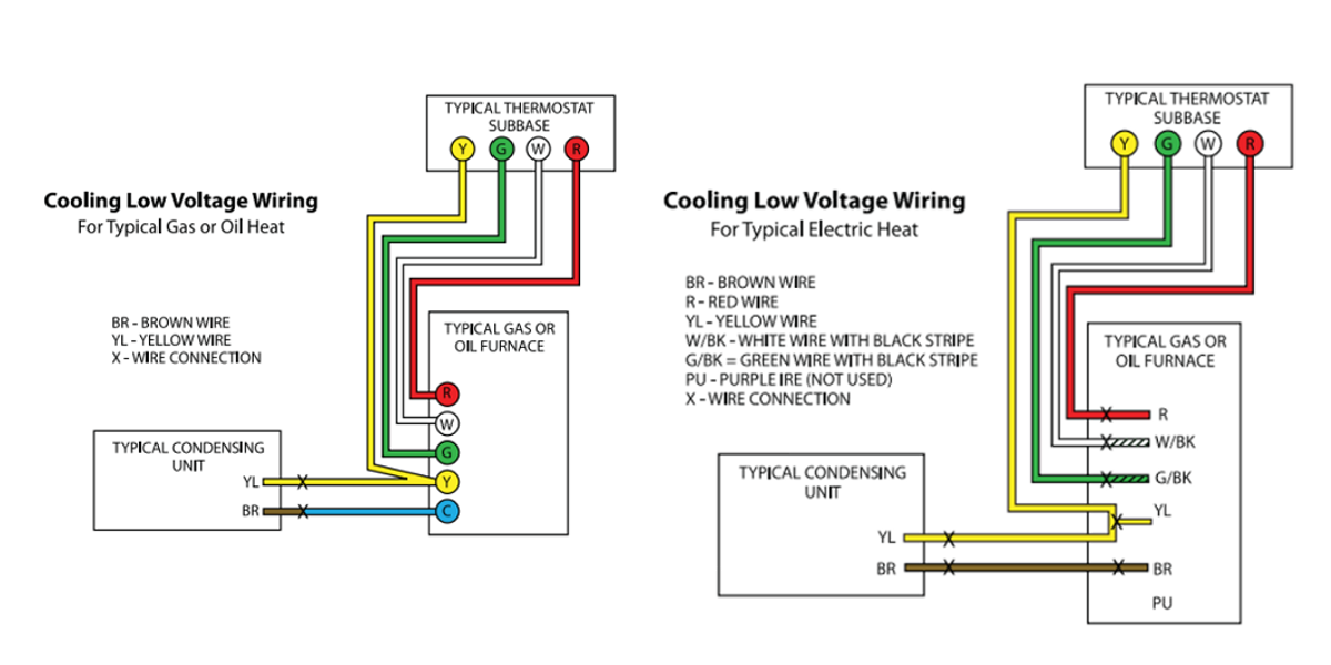
- Thermostat: The thermostat is the brain of the system, sending signals to the AC unit to turn on or off based on temperature settings. Wires for functions like heating, cooling, fan, and common (power return) are shown.
- Transformer: The transformer steps down the incoming voltage (usually 120V or 240V) to the low voltage (typically 24V AC) required for the control circuitry.
- Relays and Contactors: These are electrically operated switches that control the higher voltage components, such as the compressor and fan motors. The low voltage circuit activates the relay, which then closes the high voltage circuit.
- Safety Switches: These include components like:
- Float Switch: Detects water overflow in the condensate drain pan and shuts down the system to prevent water damage.
- Pressure Switches: Monitor refrigerant pressure and shut down the system if the pressure is too high or too low, protecting the compressor.
- Freeze Stat: Detects when the evaporator coil is freezing over and shuts the compressor down to prevent damage.
- Control Board: In newer, more sophisticated units, a control board may manage the various functions and communicate with the thermostat.
- Wiring: The diagram shows the wires connecting all of these components, often using color codes to identify the function of each wire.
- Capacitors: Often, a capacitor is used to provide starting power to fans or other motors.
Understanding the symbols used for each component is crucial for interpreting the diagram correctly.
Q: What do the different wire colors in the diagram represent?
Wire colors are used to help identify the function of each wire and to ensure correct connections are made. While there isn't a universally standardized color code across all air conditioner manufacturers, some common conventions exist:
- Red: Often used for the 24V AC "hot" wire, the positive side of the power supply.
- White: Commonly used for the 24V AC "common" wire, the neutral or return side of the power supply.
- Yellow: Often used for the "cooling" signal from the thermostat.
- Green: Typically used for the "fan" signal from the thermostat.
- Blue: May be used for the "common" wire from the thermostat or for other control signals.
- Orange: Can be used for heat pump reversing valve control.
Important: Never rely solely on wire color for identification. Always refer to the wiring diagram for your specific unit to confirm the function of each wire. Also, some installations may have used different colors than originally intended, so trace the wires back to their source to verify their function before disconnecting or reconnecting them.
Q: What are some common problems that can be diagnosed using a low voltage wiring diagram?
A low voltage wiring diagram can be invaluable in diagnosing a wide range of AC problems. Here are some common examples:
- AC Unit Not Turning On: The diagram can help trace the signal path from the thermostat to the relays/contactors that control the compressor and fan motors. You can check for voltage at different points in the circuit to pinpoint where the signal is being interrupted.
- Fan Not Working: The diagram will show the wiring connections to the fan motor relay. You can test the relay and the wiring to the fan motor to identify the cause of the problem.
- Compressor Not Working: The diagram will show the wiring connections to the compressor contactor. You can test the contactor and the wiring to the compressor to identify the cause of the problem.
- Thermostat Not Communicating: The diagram shows the wiring between the thermostat and the AC unit. You can check for loose connections, damaged wires, or a faulty thermostat.
- Safety Switches Tripping: The diagram will show the location of safety switches in the circuit. If a safety switch is tripping, the diagram can help you understand what condition is causing the switch to activate (e.g., water overflow, high pressure).
- Short Circuits: By tracing the wiring in the diagram, you can often identify potential short circuits, such as where a wire is touching a grounded surface.
- Incorrect Wiring After Repairs: If the AC unit malfunctions after a repair, the wiring diagram can be used to verify that all connections were made correctly.
By systematically checking the wiring and components according to the diagram, technicians can efficiently diagnose and resolve many common AC problems.
Q: What safety precautions should I take when working with low voltage wiring on my air conditioner?
Even though it's low voltage, safety is paramount when working with any electrical system. Follow these precautions:
- Disconnect Power: Always turn off the power to the air conditioner at the circuit breaker before working on any wiring. This is the most important safety precaution. Verify the power is off with a non-contact voltage tester.
- Use Insulated Tools: Use tools with insulated handles to prevent electrical shock.
- Never Work Alone: It's always best to have someone else present when working on electrical systems in case of an emergency.
- Wear Safety Glasses: Protect your eyes from flying debris or accidental sparks.
- Don't Work in Wet Conditions: Avoid working on electrical systems in wet or damp environments.
- Double-Check Wiring: Before restoring power, double-check all wiring connections to ensure they are secure and correct according to the wiring diagram.
- If Unsure, Call a Professional: If you are not comfortable working with electrical wiring or are unsure about any aspect of the repair, always call a qualified HVAC technician. It's better to be safe than sorry.
Q: Can I use a generic low voltage wiring diagram for my air conditioner, or do I need a specific one?
You should always use the specific low voltage wiring diagram for your air conditioner model. While some basic principles of low voltage control circuits are common across different models, the specific wiring configurations, component locations, and wire colors can vary significantly.
Using a generic diagram could lead to:
- Incorrect Wiring: Incorrect connections can damage components, cause the system to malfunction, or even create a fire hazard.
- Misdiagnosis: A generic diagram may not accurately represent the components and wiring in your unit, leading to incorrect troubleshooting and wasted time.
- Voided Warranty: Tampering with the wiring using incorrect information could void the warranty on your air conditioner.
Always take the time to locate the correct wiring diagram for your specific model before attempting any electrical work on your air conditioner.