Mini Split Condensate Pump Wiring Diagram

Mini-split systems, also known as ductless mini-split heat pumps or air conditioners, are gaining immense popularity due to their energy efficiency and ease of installation. A crucial, yet often overlooked, component of these systems is the condensate pump. This article delves into the intricacies of mini-split condensate pump wiring diagrams, offering practical guidance for homeowners, business owners, smart home enthusiasts, and HVAC professionals alike. Understanding the wiring ensures proper pump operation, prevents water damage, and contributes to the overall longevity and efficiency of your system.
Why Understanding Condensate Pump Wiring Matters
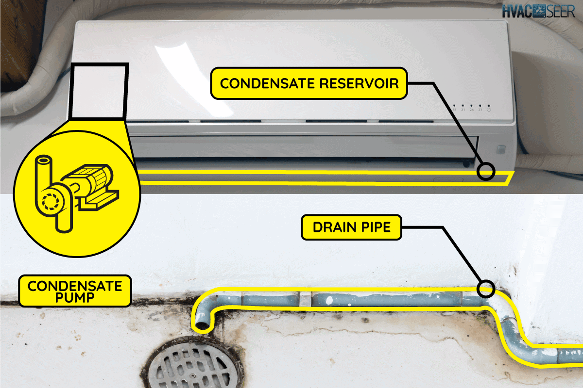
Mini-splits excel at removing moisture from the air during the cooling process. This moisture, or condensate, collects in a drain pan within the indoor unit. Gravity is usually relied upon to drain this water; however, when gravity drainage is not possible, a condensate pump is required to lift the water and move it to a suitable drain location. Improper wiring of the condensate pump can lead to several problems:
- Water Damage: A malfunctioning pump will not remove condensate, potentially leading to overflows and water damage to walls, floors, and ceilings. This can result in costly repairs and even mold growth.
- System Inefficiency: If the pump isn't working correctly, the mini-split may struggle to dehumidify effectively, forcing it to work harder and consume more energy.
- Pump Failure: Incorrect wiring can damage the pump motor, shortening its lifespan and requiring premature replacement.
- Safety Hazards: Improperly wired electrical components can pose a risk of electric shock or fire.
Therefore, understanding the condensate pump wiring diagram is paramount for successful installation, troubleshooting, and maintenance.
Decoding the Condensate Pump Wiring Diagram
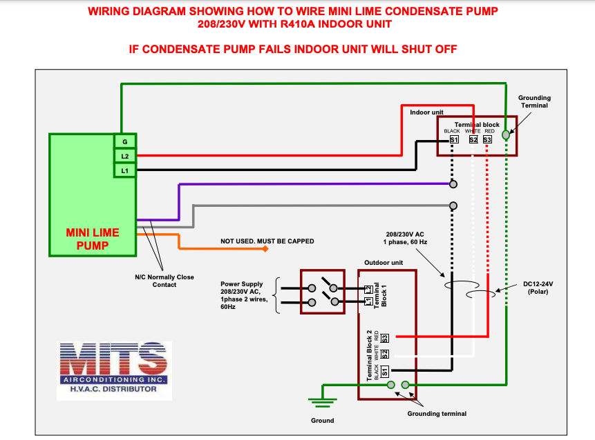
A condensate pump wiring diagram is a visual representation of how the pump's electrical components are connected. While specific diagrams vary depending on the pump manufacturer and model, some common elements are always present:
Key Components Illustrated in a Typical Diagram
- Power Supply: This shows the incoming power source (typically 110-120V AC in residential applications) and how it connects to the pump. The diagram will clearly mark the "Line" (hot), "Neutral," and "Ground" wires.
- Float Switch: The float switch is a critical component that detects the water level in the pump's reservoir. When the water level rises, the float switch activates the pump. The wiring diagram shows how the float switch is connected to the pump motor and power supply. Many pumps have two-level float switches: one to activate the pump, and a second, higher level, to trigger a safety switch.
- Pump Motor: The diagram will illustrate the connection between the float switch and the pump motor, often with specific wire colors indicated (e.g., black, white, blue).
- Alarm Circuit (Optional): Some condensate pumps include an alarm circuit that can be connected to a building management system (BMS) or a local alarm. The wiring diagram will show how to connect the alarm to the pump's control board.
- Safety Switch (Overflow Sensor): Advanced pumps have a safety switch wired into the indoor unit to shut it down if water level rise to a point where overflow is imminent. This helps prevent costly damage to property.
Common Wiring Configurations
While specific wire colors may vary, certain wiring configurations are common:
- Direct Wiring: In this configuration, the power supply is directly connected to the float switch, which in turn controls the pump motor. This is the simplest wiring arrangement.
- Relay Wiring: Some pumps utilize a relay to switch the power to the pump motor. This is often used in higher-voltage or higher-amperage applications. The diagram will show the relay coil connections and the relay contacts.
- Terminal Block Wiring: Many pumps use a terminal block for easy connection of wires. The diagram will label each terminal and indicate which wires should be connected to each.
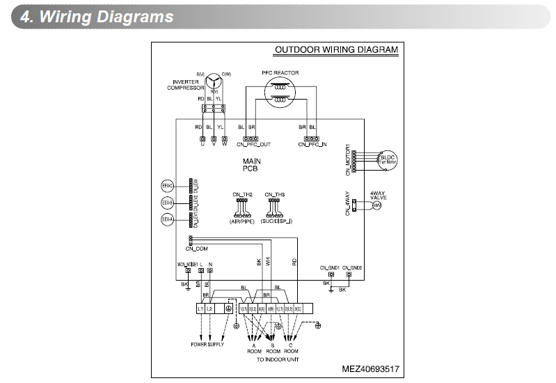
Always consult the manufacturer's wiring diagram for your specific condensate pump model. Deviating from the diagram can lead to pump failure, electrical hazards, and voided warranties.
Step-by-Step Guide to Wiring a Condensate Pump
Warning: Working with electricity can be dangerous. If you are not comfortable working with electrical wiring, consult a qualified electrician or HVAC technician.
- Safety First: Disconnect the power supply to the mini-split system at the circuit breaker before beginning any wiring work.
- Gather Tools and Materials: You will need:
- The manufacturer's wiring diagram for your condensate pump model.
- Wire strippers.
- Wire connectors (wire nuts, crimp connectors, etc.).
- Screwdrivers.
- Multimeter (for testing).
- Electrical tape.
- Identify Wires: Carefully identify each wire in the mini-split system and the condensate pump, referring to the wiring diagrams. Use a multimeter to verify the voltage and continuity of the wires.
- Connect Wires: Connect the wires according to the wiring diagram. Ensure that all connections are secure and properly insulated. Use wire connectors to join wires together, and wrap exposed connections with electrical tape. Pay close attention to the polarity of the connections.
- Connect Float Switch: Connect the float switch wires to the pump motor and power supply as indicated in the diagram. Ensure that the float switch moves freely and is not obstructed.
- Grounding: Ensure that the pump is properly grounded to prevent electrical shock. Connect the ground wire to the designated grounding terminal on the pump and the mini-split system.
- Test the Connections: Use a multimeter to test the continuity and voltage of all connections before restoring power.
- Restore Power: After verifying all connections, restore power to the mini-split system at the circuit breaker.
- Test the Pump: Pour water into the condensate pump reservoir to activate the float switch and test the pump. Ensure that the pump is operating correctly and that the water is being pumped out.
Troubleshooting Common Wiring Issues
Even with careful wiring, problems can sometimes arise. Here are some common issues and how to troubleshoot them:
- Pump Not Working:
- Check the power supply to the pump.
- Verify that the float switch is functioning correctly.
- Inspect the wiring connections for loose or damaged wires.
- Test the pump motor with a multimeter.
- Pump Running Continuously:
- Check the float switch for debris or obstructions.
- Inspect the drain line for clogs.
- Verify that the float switch is properly wired.
- Alarm Triggered:
- Check the water level in the pump reservoir.
- Inspect the drain line for clogs.
- Verify that the alarm circuit is properly wired.
Integrating with Smart Home Systems and Energy Efficiency
Smart home integration and energy efficiency are major draws for mini-split systems. Integrating your condensate pump monitoring into a smart home system adds another layer of protection and convenience. This can be achieved by using condensate pumps with integrated alarm outputs, which can then be connected to smart home hubs or sensors.
Benefits of Smart Integration:
- Remote Monitoring: Receive alerts on your smartphone or tablet if the condensate pump fails or if there is a water leak.
- Automated Shut-Off: Configure your smart home system to automatically shut off the mini-split system if the condensate pump fails, preventing water damage.
- Data Logging: Track the pump's run time and water output to identify potential problems early.
Furthermore, consider these energy-efficient practices:
- Energy Star Certification: Choose Energy Star certified mini-split systems and condensate pumps to ensure optimal energy performance. Energy Star products are independently certified to save energy and lower utility bills.
- Regular Maintenance: Clean the condensate pump reservoir and drain line regularly to prevent clogs and ensure efficient operation.
- Professional Installation: Hire a qualified HVAC technician to install your mini-split system and condensate pump correctly.
Financial Incentives: Rebates and Tax Credits
Many government agencies and utility companies offer rebates and tax credits for energy-efficient HVAC systems. Be sure to check with your local utility company and the Energy Star website for available incentives. These incentives can significantly reduce the upfront cost of installing a mini-split system and condensate pump.
The Inflation Reduction Act also provides tax credits for energy-efficient home improvements, including the installation of heat pumps. These credits can further reduce the cost of upgrading to a more energy-efficient system.
Conclusion: Investing in Proper Wiring and Maintenance
Understanding the mini-split condensate pump wiring diagram is crucial for ensuring the reliable and efficient operation of your system. By following the steps outlined in this article and consulting the manufacturer's instructions, you can properly wire the pump, troubleshoot common issues, and integrate it into a smart home system for enhanced monitoring and control. This knowledge empowers you to protect your property from water damage, reduce energy consumption, and maximize the lifespan of your mini-split system, all while enjoying the comfort and cost savings that ductless systems provide.