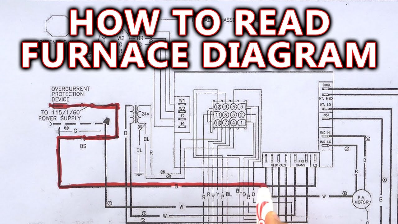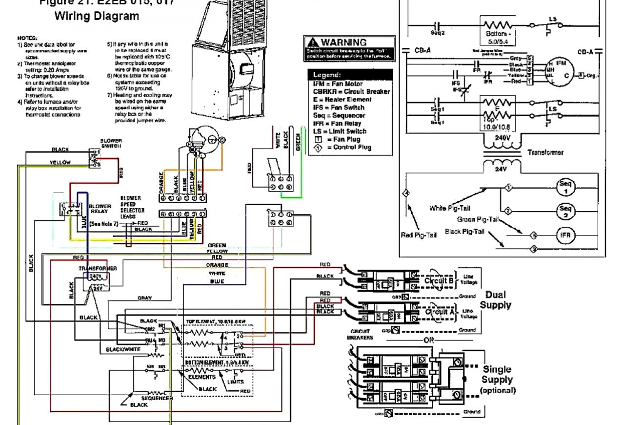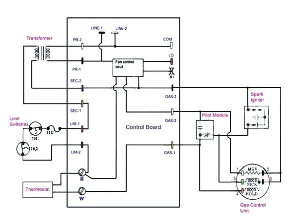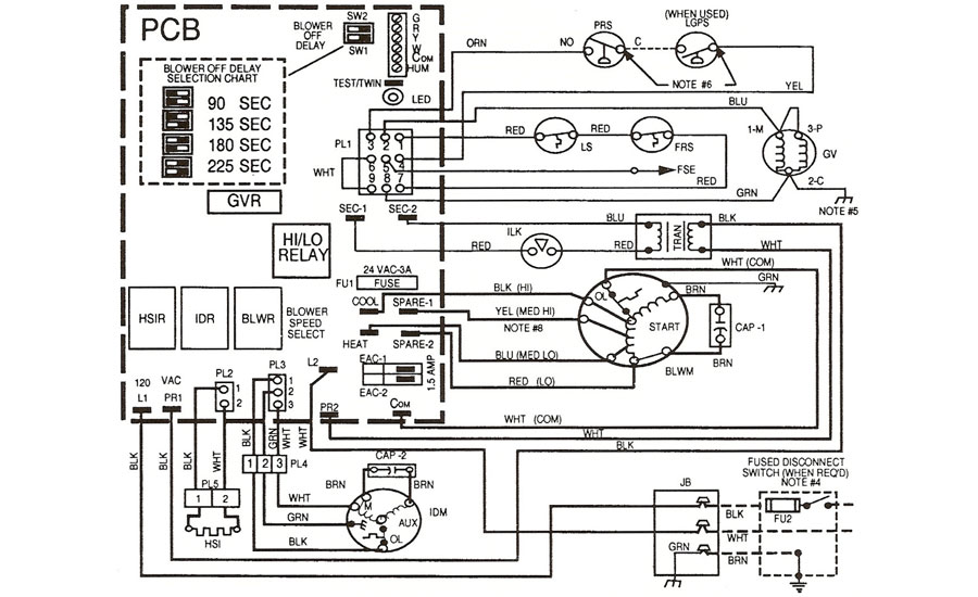
Old Gas Furnace Wiring Diagram
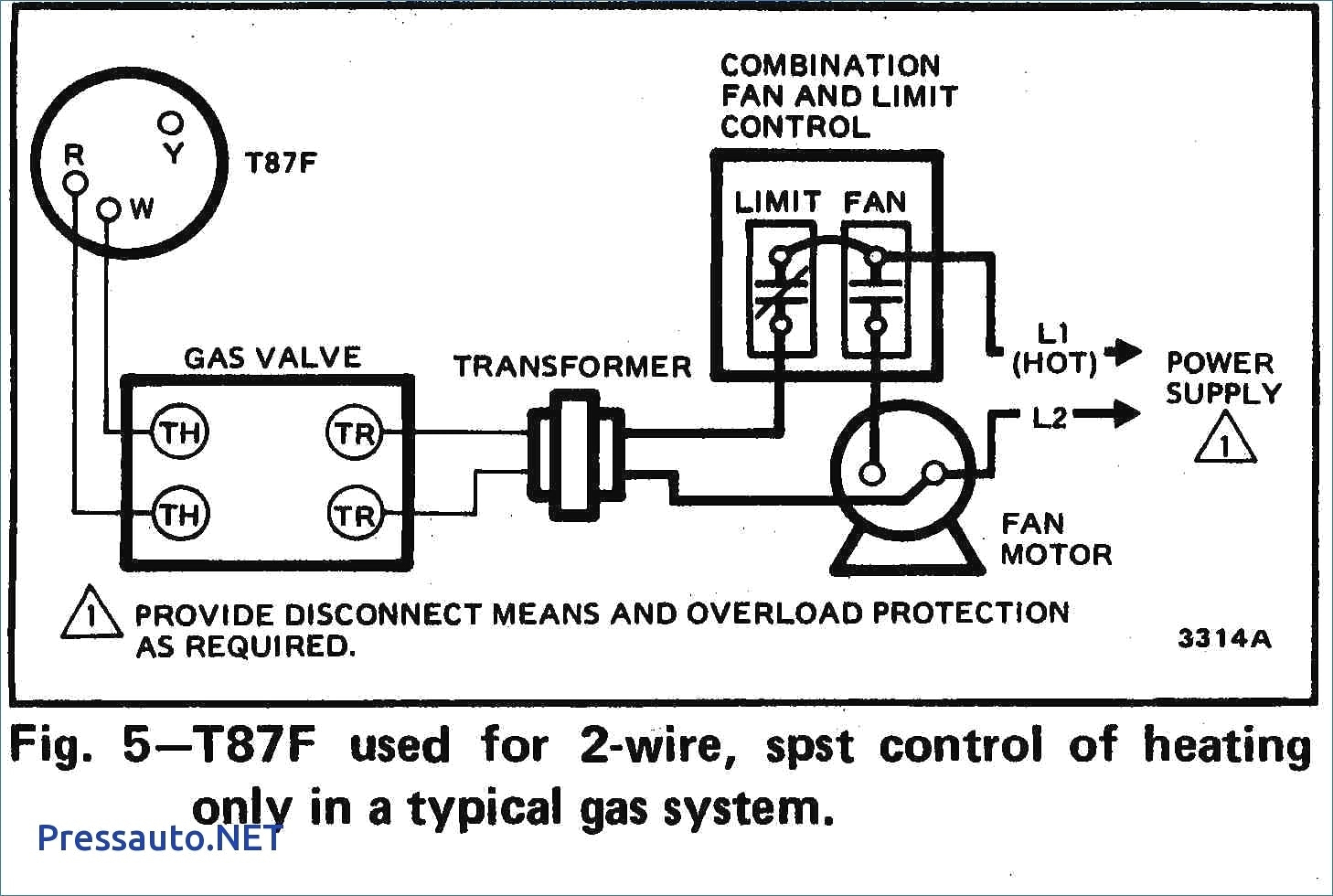
Decoding Your Old Gas Furnace Wiring Diagram: A Homeowner's Guide
Understanding your old gas furnace wiring diagram can be invaluable for diagnosing common issues and performing basic maintenance. However, remember that working with gas and electricity can be dangerous. If you are uncomfortable at any point, contact a qualified HVAC technician.
Why Bother with the Wiring Diagram?
Your furnace wiring diagram is essentially a roadmap of its electrical system. It shows how various components connect and interact. Having a grasp of this allows you to:
- Troubleshoot problems: Identify potential faulty components.
- Understand control circuits: Learn how the thermostat signals the furnace to start and stop.
- Perform basic repairs: Safely replace a faulty component like a transformer.
- Communicate effectively with HVAC techs: Describe the problem accurately.
Finding Your Wiring Diagram
The wiring diagram is usually located inside the furnace cabinet. Look for it:
- On the inside of the blower compartment door.
- Attached to the furnace wall near the control board.
- In the furnace's original documentation (unlikely, but worth checking!).
If you can’t find a physical diagram, try searching online using your furnace's model number. Many manufacturers offer downloadable PDFs of their manuals and diagrams.
Understanding the Basic Symbols and Components
Wiring diagrams use symbols to represent electrical components. Here are some common ones:
- Transformer: Often represented by two interlocking coils.
- Relay: Shown as a coil and a switch.
- Limit Switch: Depicted as a switch with a temperature-sensitive element.
- Fuse: A line with a jagged break in it.
- Motor: A circle with an "M" inside.
- Thermostat: A switch with connections for different wires (R, W, G, Y, C).
- Gas Valve: Represented by a solenoid symbol.
- Flame Sensor: Typically shown as a rod-like element.
Common components you'll see in the diagram include:
- Transformer: Steps down the voltage from 120V to 24V for the control circuit.
- Control Board: The brain of the furnace, managing the sequence of operations.
- Thermostat: Controls the heating and cooling cycles.
- Gas Valve: Controls the flow of gas to the burners.
- Ignitor: Heats up to ignite the gas. Can be a hot surface ignitor or a spark ignitor.
- Flame Sensor: Detects the presence of a flame and prevents the gas valve from shutting off prematurely.
- Blower Motor: Circulates air through the furnace and ductwork.
- Draft Inducer Motor: Creates negative pressure in the combustion chamber to ensure proper venting.
- Limit Switches: Safety devices that shut off the furnace if it overheats.
- Rollout Switches: Another type of safety switch that detects flames rolling out of the burner area.
- Fuse: Protects the electrical components from overcurrent.
Tracing a Circuit: A Step-by-Step Approach
Let's say you suspect a problem with the ignitor. Here's how you might use the wiring diagram to troubleshoot:
- Locate the ignitor: Find the symbol for the ignitor on the diagram.
- Trace the wiring: Follow the wires connected to the ignitor back to their source, usually the control board or a relay.
- Identify intermediate components: Note any switches, fuses, or relays in the circuit. These could be potential points of failure.
- Test for voltage: Using a multimeter, check for voltage at the ignitor terminals when the furnace is supposed to be igniting. If there's no voltage, trace back through the circuit, testing each component until you find the break.
Essential Tools for Troubleshooting
- Multimeter: For measuring voltage, current, and resistance.
- Screwdrivers: Both Phillips and flathead.
- Wire Strippers/Crimpers: For working with wires.
- Pliers: For gripping and manipulating components.
- Voltage Tester: A non-contact voltage tester is a good safety tool.
- Flashlight: For illuminating dark areas.
- Wiring Diagram: The most important tool!
Common Furnace Problems and Wiring Diagram Clues
- Furnace Won't Turn On:
- Check the thermostat settings and batteries.
- Inspect the main power switch to the furnace.
- Look for a tripped breaker in the electrical panel.
- Use the wiring diagram to trace the power supply to the control board. A faulty transformer can also cause this issue.
- Blower Fan Not Working:
- Check the blower motor capacitor.
- Examine the blower motor relay on the control board.
- Trace the wiring from the blower motor back to the control board.
- A faulty blower motor will also cause this.
- Furnace Cycles On and Off Quickly (Short Cycling):
- Check the flame sensor. A dirty or faulty flame sensor will cause the furnace to shut off prematurely.
- Inspect the limit switches. A tripped limit switch indicates an overheating problem.
- Look at the wiring to the gas valve.
- No Heat:
- Make sure the gas valve is open.
- Check for proper ignitor function using your diagram to trace the electrical path.
- A faulty flame sensor could be the cause.
Safety First!
Always turn off the power to the furnace at the breaker before working on any electrical components.
- Turn off the gas supply before working on the gas valve or any gas-related components.
- Use insulated tools to prevent electrical shock.
- Double-check your wiring before restoring power.
- Wear safety glasses to protect your eyes.
When to Call a Professional
While you can handle some basic troubleshooting and repairs, certain tasks are best left to a qualified HVAC technician:
- Working with gas lines: Gas leaks are dangerous and require specialized equipment and training.
- Replacing the control board: This requires programming and careful calibration.
- Troubleshooting complex issues: If you've spent a significant amount of time troubleshooting and still can't identify the problem, it's time to call for help.
- Any work involving the heat exchanger: Cracks or leaks in the heat exchanger can release deadly carbon monoxide.
Cost Estimates for Common Repairs
These are rough estimates and can vary depending on your location and the complexity of the job:
- Flame Sensor Replacement: $75 - $150
- Ignitor Replacement: $100 - $250
- Limit Switch Replacement: $100 - $200
- Blower Motor Capacitor Replacement: $75 - $150
- Transformer Replacement: $150 - $300
- Gas Valve Replacement: $250 - $500
- Control Board Replacement: $300 - $700+
Important Note: These prices typically include labor costs. Parts alone will be significantly cheaper if you choose to DIY.
Final Thoughts
Understanding your old gas furnace wiring diagram empowers you to diagnose and potentially fix simple problems. Always prioritize safety and don't hesitate to call a professional when needed. Remember, a well-maintained furnace is a safe and efficient furnace.