Schematic Diagram Of Chilled Water System

Chilled water systems are a critical part of many commercial and industrial buildings, providing efficient and reliable cooling for large spaces. Understanding how they work can be beneficial for building owners, facility managers, and anyone involved in HVAC maintenance. This guide will walk you through a schematic diagram of a typical chilled water system, explaining each component and its function in a clear and accessible manner.
What is a Chilled Water System?
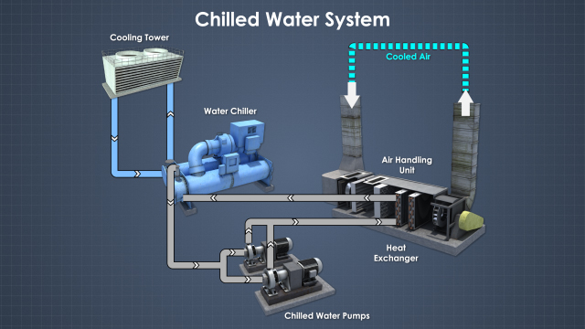
A chilled water system is a centralized cooling system that uses chilled water to cool air within a building. Instead of each room or zone having its own individual air conditioner, a central chiller cools water, which is then circulated through pipes to air handling units (AHUs) located throughout the building. These AHUs use the cold water to cool air, which is then distributed through the building's ductwork.
Think of it like a central heating system, but for cooling. Instead of hot water, we're dealing with chilled water. This approach is more energy-efficient and easier to manage than having numerous individual air conditioning units, especially in large buildings.
Understanding the Schematic Diagram
A schematic diagram is a simplified representation of the chilled water system, showing the major components and their interconnections. It's essentially a roadmap for the system. Let's break down the key elements typically found in a chilled water system schematic:
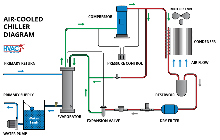
1. Chiller
The chiller is the heart of the chilled water system. Its primary function is to cool the water that will be circulated throughout the building. Chillers come in various types, including:
- Vapor-compression chillers: These are the most common type and use a refrigerant cycle to cool the water. Think of refrigerant as the 'blood' of your AC system, carrying heat from inside to outside.
The chiller schematic representation will typically show the chiller unit with connections for chilled water supply and return, as well as condenser water connections (which we'll discuss later). It will also include connections for power and control.
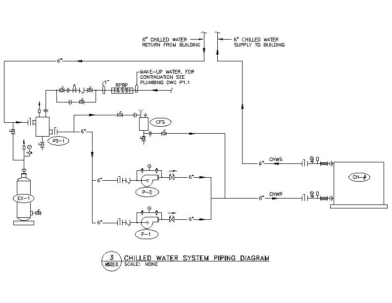
2. Chilled Water Pump(s)
The chilled water pump(s) are responsible for circulating the chilled water from the chiller to the air handling units and back. There are often multiple pumps to provide redundancy and handle varying cooling loads. They ensure constant and reliable flow of the chilled water for optimal cooling.
The schematic shows the pump with arrows indicating the direction of water flow. Sometimes, the diagram will show the pump’s variable frequency drive (VFD), which controls the pump speed and thus the flow rate, optimizing energy efficiency.
3. Air Handling Units (AHUs)
Air handling units (AHUs) are located throughout the building and are responsible for cooling the air that is circulated through the ductwork. Each AHU contains a cooling coil, which is where the chilled water passes through. As air is blown across the cooling coil, heat is transferred from the air to the chilled water, effectively cooling the air.
The schematic will illustrate the AHU with connections for chilled water supply and return. It usually includes a representation of the cooling coil and the air duct connections.
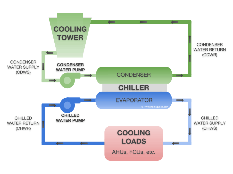
4. Cooling Tower
The cooling tower is used to reject heat from the chiller's condenser. As the chiller cools the water, it also generates heat, which needs to be dissipated. The cooling tower accomplishes this by evaporating a small amount of water, which cools the remaining water. This cooled water is then circulated back to the chiller's condenser, completing the cycle.
Think of the cooling tower as a giant radiator for the chiller. It removes the excess heat produced during the cooling process.
The schematic shows the cooling tower with connections for condenser water supply and return. It also indicates the presence of fans to facilitate evaporation and heat rejection.
5. Condenser Water Pump(s)
The condenser water pump(s) circulate the water between the chiller's condenser and the cooling tower. This is a separate loop from the chilled water loop.
Similar to the chilled water pumps, the schematic shows the condenser water pumps with arrows indicating the direction of flow. Again, VFDs may be present to control pump speed and optimize energy usage.
6. Expansion Tank
The expansion tank accommodates changes in water volume due to temperature fluctuations. As water heats up, it expands, and as it cools down, it contracts. The expansion tank provides a buffer to prevent pressure build-up or vacuum in the system.
The schematic will show the expansion tank connected to the chilled water loop. It's a relatively simple component, but essential for maintaining system stability.
7. Chemical Treatment System
A chemical treatment system is essential to maintain water quality and prevent corrosion, scaling, and biological growth within the chilled water system. These systems typically include chemical feeders and monitoring equipment.
While not always explicitly shown, the schematic diagram might include a note indicating the presence of a chemical treatment system.
8. Piping and Valves
The piping connects all the components of the chilled water system, allowing the water to flow from one component to another. Valves are used to control the flow of water, isolate sections of the system for maintenance, and balance the system.
The schematic will show the piping with different line types to indicate supply and return lines. Valves are represented by symbols, indicating their type (e.g., gate valve, ball valve, butterfly valve).
9. Control System
The control system is the "brain" of the chilled water system. It monitors and controls the operation of all the components, ensuring that the system operates efficiently and effectively. The control system typically includes sensors, controllers, and actuators.
The schematic might show a simplified representation of the control system, indicating the connection of sensors (e.g., temperature sensors, pressure sensors, flow sensors) to the controller. The controller then sends signals to actuators, which control the operation of valves, pumps, and the chiller.
How the System Works: A Step-by-Step Explanation
- The chiller cools the water to the desired temperature (e.g., 44°F).
- The chilled water pump circulates the chilled water through the chilled water loop to the AHUs.
- At the AHUs, the chilled water passes through the cooling coils, cooling the air that is circulated through the building.
- The warmed water returns to the chiller to be cooled again.
- The chiller rejects heat to the condenser water loop.
- The condenser water pump circulates the water through the condenser water loop to the cooling tower.
- At the cooling tower, the heat is rejected to the atmosphere through evaporation.
- The cooled condenser water returns to the chiller to absorb more heat.
- The control system monitors and controls the operation of all the components, ensuring that the system operates efficiently and effectively.
Benefits of Chilled Water Systems
- Energy Efficiency: Centralized cooling is typically more energy-efficient than individual air conditioning units, especially in large buildings.
- Precise Temperature Control: Chilled water systems provide precise temperature control throughout the building, ensuring occupant comfort.
- Improved Air Quality: Centralized air handling units can provide better air filtration and ventilation than individual air conditioning units, improving indoor air quality.
- Reduced Maintenance: Centralized systems are easier to maintain than numerous individual units.
- Longer Lifespan: Well-maintained chilled water systems can have a longer lifespan than individual air conditioning units.
Key Considerations When Reviewing a Schematic
- Flow Rates: The schematic should indicate the design flow rates for both the chilled water and condenser water loops. These values are crucial for proper system operation.
- Operating Pressures: The schematic should also specify the design operating pressures for each loop.
- Temperature Differentials: Pay attention to the temperature difference between the supply and return water in both loops. This indicates the system's efficiency.
- Control Strategy: Understand how the control system is designed to operate the system under different load conditions.
- Safety Devices: Identify the location of safety devices such as pressure relief valves and flow switches.
Conclusion
Understanding the schematic diagram of a chilled water system is essential for effective operation, maintenance, and troubleshooting. By familiarizing yourself with the key components and their functions, you can gain a better understanding of how the system works and make informed decisions regarding its operation and maintenance. This knowledge empowers you to optimize system performance, reduce energy consumption, and ensure reliable cooling for your building. Remember to consult with qualified HVAC professionals for any complex issues or modifications to your chilled water system. Always prioritize safety and adhere to relevant industry standards and regulations.