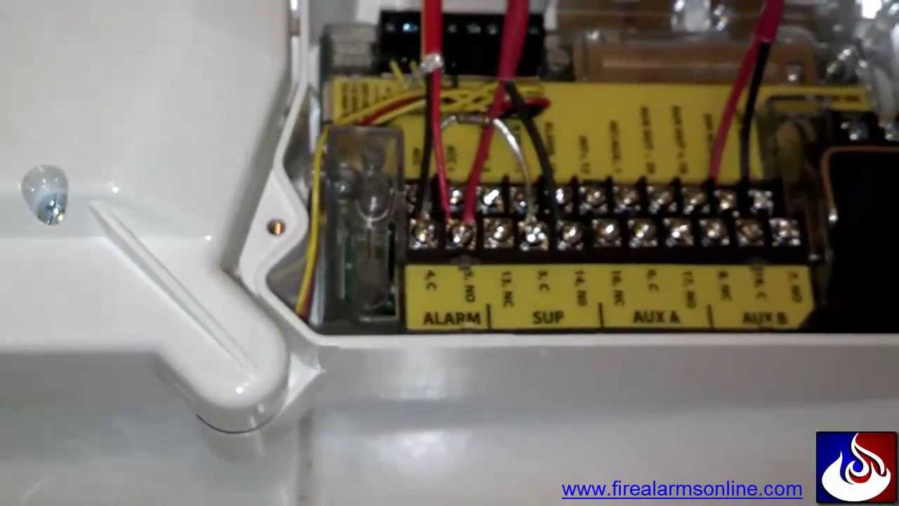
System Sensor Duct Smoke Detector Wiring Diagram

Duct smoke detectors are a critical component of your HVAC system, providing early warning of fire and potentially saving lives. But like any electronic device, they can sometimes malfunction. One common problem homeowners face is the persistent sounding of a fire alarm, seemingly without any smoke present, or the detector simply failing to operate as expected. This can be frustrating and disruptive, leading to unnecessary worry and potential fines if the fire department is called out unnecessarily. This article provides a step-by-step guide to troubleshooting your System Sensor duct smoke detector wiring, helping you diagnose common problems and implement simple fixes. However, remember to always prioritize safety and know when to call a qualified professional.
Understanding Your System Sensor Duct Smoke Detector
Before diving into troubleshooting, it's important to understand the basic components and wiring of a System Sensor duct smoke detector. These detectors are typically installed directly within your HVAC ductwork, sampling the air flowing through the system. They connect to your fire alarm control panel (FACP) and can trigger an alarm if smoke is detected.
Key Components:
- Detector Head: This is the part that actually senses the smoke. It contains the sensing chamber and electronics.
- Housing: The metal enclosure that protects the detector head and mounts to the ductwork.
- Sampling Tubes: These tubes extend into the ductwork to draw air samples into the detector.
- Wiring Terminals: Located inside the housing, these terminals provide the connections for power, alarm signals, and other functions.
- Relay Contacts: Some models include relay contacts that can be used to control dampers, shut down HVAC systems, or activate other devices.
Common Wiring Configurations
While specific wiring configurations can vary depending on the model and the overall fire alarm system, some common wiring arrangements include:
- Two-Wire System: Power and alarm signals share the same two wires.
- Four-Wire System: Separate pairs of wires are used for power and alarm signals.
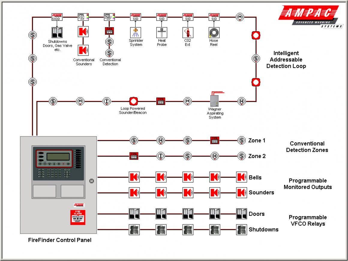
- Addressable System: Each detector has a unique address and communicates digitally with the FACP.
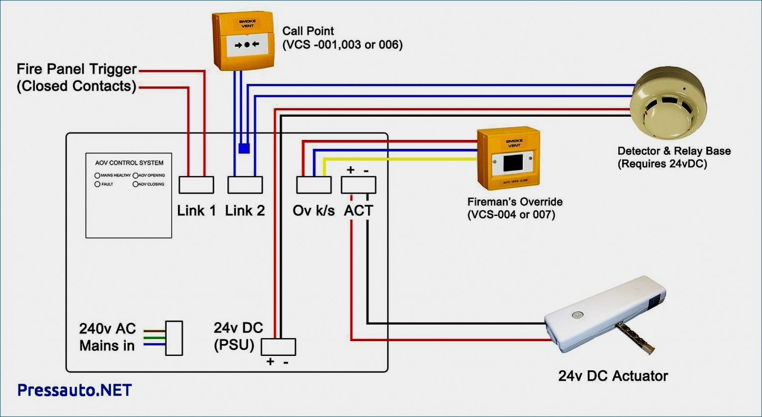
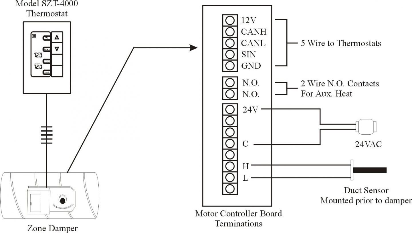
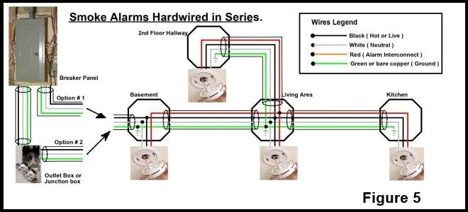
Consult your detector's manual or the fire alarm system documentation for the exact wiring diagram specific to your installation. This information is crucial for accurate troubleshooting.
Step-by-Step Troubleshooting Guide
Let's walk through a methodical troubleshooting process to identify and resolve common wiring-related issues. Always turn off the power to the HVAC system and the fire alarm system before starting any electrical work. This is a critical safety precaution.
Step 1: Gather Information
Before you start disconnecting wires, gather as much information as possible:
- Detector Model Number: Locate the model number on the detector housing. This is essential for finding the correct wiring diagram.
- System Documentation: Review your fire alarm system documentation, including wiring diagrams and installation instructions.
- Recent Events: Has anything changed recently? Was there a power outage, HVAC maintenance, or other event that might have affected the system?
- Specific Symptoms: What exactly is happening? Is the alarm sounding continuously, intermittently, or not at all? Are there any error messages on the FACP?
Step 2: Visual Inspection
Perform a thorough visual inspection of the detector and its wiring:
- Check for Loose Connections: Carefully examine all wiring connections at the detector terminals and the FACP. Make sure all wires are securely fastened. Gently tug on each wire to confirm it's properly connected.
- Look for Damaged Wiring: Inspect the wires for cuts, abrasions, or other damage to the insulation. Replace any damaged wiring.
- Check for Corrosion: Look for signs of corrosion on the wiring terminals or connectors. Clean any corroded connections with a wire brush or contact cleaner.
- Verify Proper Installation: Ensure the detector is properly mounted and that the sampling tubes are correctly positioned within the ductwork. Blocked or misaligned sampling tubes can affect the detector's performance.
Step 3: Power Verification
Using a multimeter, verify that the detector is receiving the correct voltage. Consult the detector's specifications for the required voltage range.
- Measure Voltage: Set your multimeter to the appropriate DC voltage range and carefully measure the voltage at the power terminals of the detector.
- Compare to Specifications: Compare the measured voltage to the voltage range specified in the detector's manual. If the voltage is outside the specified range, investigate the power supply to the detector. This may involve checking the FACP or other power sources.
- Check Polarity: Ensure that the positive and negative wires are connected correctly to the detector terminals. Reverse polarity can damage the detector.
Step 4: Wiring Continuity Test
Perform a continuity test on the wiring to check for broken or shorted wires. This requires disconnecting the wires from the detector and the FACP.
- Disconnect Wires: Turn off power first! Disconnect the wires from both the detector terminals and the FACP terminals. Label each wire clearly to ensure you can reconnect them correctly later.
- Set Multimeter: Set your multimeter to the continuity testing mode (usually indicated by a diode symbol or a sound).
- Test Each Wire: Place one probe of the multimeter on one end of a wire and the other probe on the other end. The multimeter should indicate continuity (a low resistance reading or a beep) if the wire is intact. If the multimeter shows no continuity, the wire is broken and needs to be replaced.
- Check for Shorts: Test for shorts between different wires. Place one probe on one wire and the other probe on another wire. The multimeter should show no continuity (a high resistance reading). If the multimeter indicates continuity, there is a short between the wires, which needs to be located and corrected.
Step 5: Tamper Switch Check
Most duct smoke detectors have a tamper switch that is activated when the detector head is removed from the base. A faulty tamper switch can cause false alarms.
- Locate Tamper Switch: Find the tamper switch on the detector base. It is usually a small lever or button.
- Inspect the Switch: Make sure the tamper switch is properly engaged when the detector head is installed.
- Test the Switch: Use a multimeter to test the continuity of the tamper switch. The switch should be closed (showing continuity) when the detector head is installed and open (showing no continuity) when the detector head is removed. If the tamper switch is faulty, it may need to be cleaned or replaced.
Step 6: Alarm Relay Test (If Applicable)
If your detector uses relays to control dampers or other equipment, test the relays to ensure they are functioning correctly.
- Identify Relay Contacts: Locate the relay contacts on the detector wiring diagram.
- Test Relay Operation: Simulate an alarm condition (refer to the detector's manual for how to do this). Use a multimeter to check the state of the relay contacts. The contacts should change state when the alarm is triggered.
- Verify Controlled Equipment: Confirm that the equipment controlled by the relay (e.g., dampers, HVAC system) responds correctly when the alarm is triggered.
Step 7: Reassemble and Test
After completing the troubleshooting steps and making any necessary repairs, carefully reassemble the detector and test its operation.
- Reconnect Wires: Reconnect all wires to the detector terminals and the FACP terminals, ensuring they are securely fastened and connected to the correct terminals based on your wiring diagram.
- Restore Power: Turn the power back on to the HVAC system and the fire alarm system.
- Test the Detector: Perform a functional test of the detector according to the manufacturer's instructions. This typically involves introducing simulated smoke into the detector and verifying that it triggers an alarm. Never use real fire or smoke for testing! Some detectors have a test button that can be used for this purpose.
- Monitor the System: Monitor the system for any further problems. If the alarm continues to sound or the detector fails to operate correctly, further troubleshooting or professional assistance may be required.
When to Call a Professional
While this guide provides a comprehensive approach to troubleshooting System Sensor duct smoke detector wiring, there are certain situations where you should always call a qualified fire alarm technician. Attempting to repair complex electrical systems without proper training can be dangerous and may void your warranty or violate local codes.
Call a Professional If:
- You are uncomfortable working with electricity.
- You cannot identify the problem.
- The problem persists after performing the troubleshooting steps outlined above.
- You suspect a problem with the FACP or other components of the fire alarm system.
- The detector is part of a commercial or industrial fire alarm system. Commercial systems often require specialized knowledge and certifications.
- The wiring is complex or unfamiliar.
- You encounter any signs of arcing, burning, or other electrical hazards.
- You are required by local codes or regulations to have a qualified technician perform the work.
- If the detector fails the sensitivity test as outline in the manufactures instructions.
Always remember that your safety is paramount. Do not hesitate to seek professional assistance if you are unsure about any aspect of the troubleshooting process.
Preventative Maintenance
Regular preventative maintenance can help prevent problems with your duct smoke detector and ensure its reliable operation.
- Clean the Detector: Clean the detector head and housing regularly to remove dust and debris. Use a soft cloth or vacuum cleaner with a brush attachment.
- Test the Detector Regularly: Perform a functional test of the detector at least once a year, or more frequently if recommended by the manufacturer or local codes.
- Replace the Detector: Duct Smoke detectors have a lifespan of 10 years. Replace the detectors every 10 years, or as recommended by the manufacturer. The date of manufacture is usually stamped on the back of the detector.
- Inspect Wiring: Periodically inspect the wiring for damage or corrosion.
- Maintain Records: Keep records of all maintenance and testing activities.
By following these troubleshooting steps and preventative maintenance tips, you can help ensure that your System Sensor duct smoke detector is functioning properly and providing reliable protection for your home or business.