Two Stage Heat Pump Thermostat Wiring

Understanding and properly wiring a thermostat to a two-stage heat pump is crucial for optimal home comfort, energy efficiency, and system longevity. Unlike single-stage systems that operate at only one output level, two-stage heat pumps offer greater control and responsiveness to changing heating and cooling demands. This article delves into the intricacies of thermostat wiring for two-stage heat pump systems, catering to homeowners, HVAC technicians, and facility managers alike.
Two-Stage Heat Pump Basics
Before diving into wiring, let's clarify what a two-stage heat pump is and why it's beneficial. In essence, a two-stage heat pump has two levels of operation: a lower stage for milder weather and a higher stage for colder temperatures. Think of it like a car with two gears – one for cruising and one for accelerating uphill.
Benefits of a two-stage system include:
- Improved Comfort: Two-stage systems maintain more consistent temperatures, eliminating the temperature swings common with single-stage units. The lower stage runs more frequently, providing gentler, more even heating or cooling.
- Enhanced Energy Efficiency: By running at a lower capacity most of the time, the system uses less energy. This translates to lower utility bills, especially during moderate weather conditions. These systems often boast higher Seasonal Energy Efficiency Ratio (SEER) ratings for cooling and Heating Seasonal Performance Factor (HSPF) ratings for heating compared to their single-stage counterparts.
- Better Dehumidification: When cooling, the lower stage runs longer, removing more moisture from the air. This is especially beneficial in humid climates.
- Quieter Operation: The lower stage typically operates at a reduced fan speed, resulting in quieter operation.
- Extended Equipment Lifespan: Less stress on the compressor and other components can potentially extend the lifespan of the unit.
Understanding Thermostat Terminals
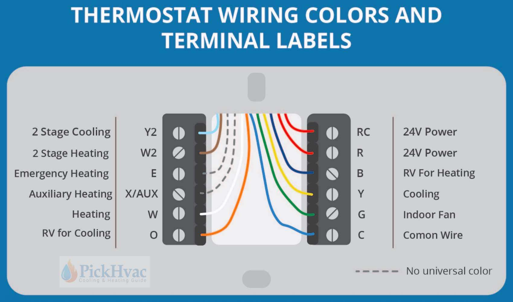
The thermostat serves as the control center for your HVAC system. Understanding the terminals and their functions is key to correct wiring. Here's a breakdown of common terminals found on thermostats for two-stage heat pumps:
- R (Red): 24V power supply. Often jumpered to Rc.
- Rc (Red Cooling): 24V power supply for cooling.
- Rh (Red Heating): 24V power supply for heating. If you only have one R wire, it often connects to Rh.
- C (Common): Common wire (neutral) for the 24V power supply. This wire is essential for many smart thermostats and provides stable power.
- Y1 (Yellow 1st Stage Cooling): Activates the first stage of cooling.
- Y2 (Yellow 2nd Stage Cooling): Activates the second stage of cooling.
- G (Green): Fan. Controls the indoor blower fan.
- O/B (Orange/Blue): Reversing valve. Determines whether the heat pump operates in heating or cooling mode. The specific designation (O or B) depends on the manufacturer; 'O' energizes in cooling mode, while 'B' energizes in heating mode. Consult your system's documentation to determine the correct setting.
- W1 (White 1st Stage Heating): Activates the first stage of heating (heat pump or auxiliary heat).
- W2/Aux (White 2nd Stage Heating/Auxiliary Heat): Activates the second stage of heating or auxiliary/emergency heat (typically electric resistance heat).
- E (Emergency Heat): Engages emergency heat, usually electric resistance coils, bypassing the heat pump entirely.
- L (Fault Indicator): Indicates a system fault.
- S1, S2 (Sensor): Used for remote temperature sensors or other specific features depending on the thermostat model.
Wiring Scenarios and Diagrams
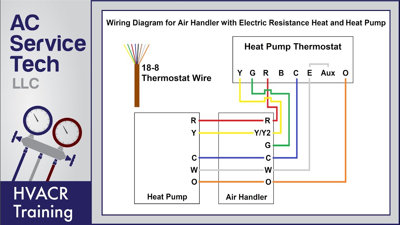
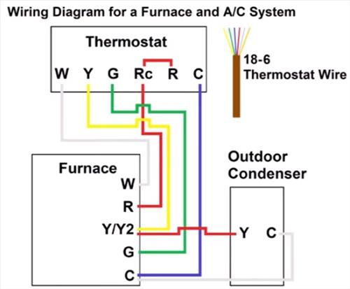
Wiring configurations can vary depending on the specific equipment and thermostat model. Always consult the wiring diagrams provided with your thermostat and heat pump. Here are a couple of common scenarios:
Scenario 1: Standard Two-Stage Heat Pump with Auxiliary Heat
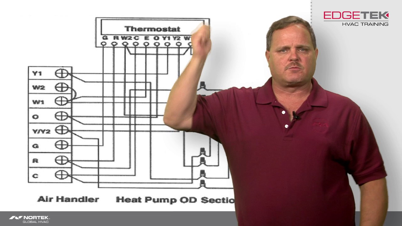
In this common setup, the heat pump handles most of the heating and cooling, with auxiliary heat kicking in when the heat pump can't keep up (e.g., extremely cold weather). Here's a typical wiring scheme:
- R: To R terminal on thermostat
- C: To C terminal on thermostat
- Y1: To Y1 terminal on thermostat
- Y2: To Y2 terminal on thermostat
- G: To G terminal on thermostat
- O/B: To O/B terminal on thermostat (configure for O or B based on your heat pump)
- W1: To W1 terminal on thermostat
- W2/Aux: To W2/Aux terminal on thermostat
Scenario 2: Two-Stage Heat Pump with Fossil Fuel Backup
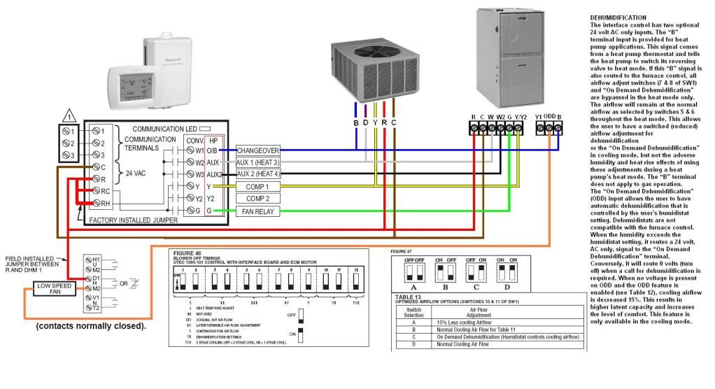
Some homes use a heat pump as the primary heating source and a furnace (gas or oil) as a backup. This is known as a dual-fuel system. In this case, the wiring is more complex and typically involves a control module to manage the switchover between the heat pump and furnace. The thermostat wiring diagram will depend heavily on the specific control module and equipment used. Consult the documentation carefully.
Step-by-Step Wiring Guide
Safety First: Always turn off power to the HVAC system at the circuit breaker before working with any wiring.
- Document Existing Wiring: Before disconnecting anything, take clear pictures of the existing wiring at both the thermostat and the equipment end. This serves as a valuable reference point.
- Label Wires: Use wire labels to mark each wire before disconnecting it. This will prevent confusion during reconnection.
- Disconnect Old Thermostat: Carefully disconnect the wires from the old thermostat.
- Install New Thermostat: Mount the new thermostat on the wall.
- Connect Wires: Refer to your wiring diagram and connect the wires to the corresponding terminals on the new thermostat. Double-check each connection.
- Configure Thermostat: Set up the thermostat according to the manufacturer's instructions, including setting the heat pump type (O or B) and any other relevant parameters.
- Power On: Restore power to the HVAC system at the circuit breaker.
- Test System: Test the system in both heating and cooling modes to ensure it's functioning correctly. Check that both stages of the heat pump are working, as well as the auxiliary heat (if applicable).
Troubleshooting Common Issues
Problem: Heat pump only runs in one stage.
Possible Causes:
- Incorrect wiring. Double-check all connections.
- Thermostat not configured correctly for two-stage operation.
- Faulty thermostat or heat pump control board.
Problem: Auxiliary heat comes on too often.
Possible Causes:
- Thermostat temperature settings too high.
- Incorrect thermostat settings for auxiliary heat lockout temperature.
- Faulty outdoor temperature sensor (if used).
Problem: System not heating or cooling at all.
Possible Causes:
- Power not restored to the system.
- Incorrect wiring.
- Blown fuse or tripped circuit breaker.
- Faulty thermostat or heat pump.
Professional Installation and Considerations
While some homeowners may be comfortable wiring a thermostat themselves, it's often best to hire a qualified HVAC technician, especially for complex systems or if you're unsure about any aspect of the process. A professional can ensure proper wiring, configuration, and system operation, maximizing efficiency and preventing costly damage.
Cost Considerations: The cost of a two-stage heat pump is typically higher than a single-stage unit. Thermostats for two-stage systems may also be slightly more expensive. However, the long-term energy savings can often offset the initial investment. The lifespan of a well-maintained heat pump is generally 15-20 years.
Efficiency Ratings: Look for heat pumps with high SEER and HSPF ratings to maximize energy savings. Energy Star-certified models meet strict efficiency guidelines.
Maintenance: Regular maintenance, including filter changes and coil cleaning, is crucial for optimal performance and longevity. A qualified HVAC technician should inspect and service the system annually.
By understanding the intricacies of thermostat wiring for two-stage heat pumps, homeowners, HVAC technicians, and facility managers can ensure optimal comfort, energy efficiency, and system longevity. Remember to prioritize safety, consult equipment documentation, and seek professional assistance when needed.