Wiring Diagram For Coleman Furnace
Understanding Your Coleman Furnace Wiring Diagram: A Homeowner's Guide
Furnace problems can be frustrating, especially during the cold months. While some issues require a professional HVAC technician, understanding your Coleman furnace wiring diagram can empower you to troubleshoot basic problems and communicate effectively with professionals. This guide provides an overview of interpreting wiring diagrams, identifying common components, and performing basic troubleshooting. However, always prioritize safety and consult a qualified technician for complex repairs.
Why You Need a Wiring Diagram
A wiring diagram is a roadmap of your furnace's electrical system. It shows how all the components are connected. It's essential for:
- Troubleshooting electrical issues.
- Replacing components safely and correctly.
- Understanding the sequence of operation.
- Communicating effectively with HVAC technicians.
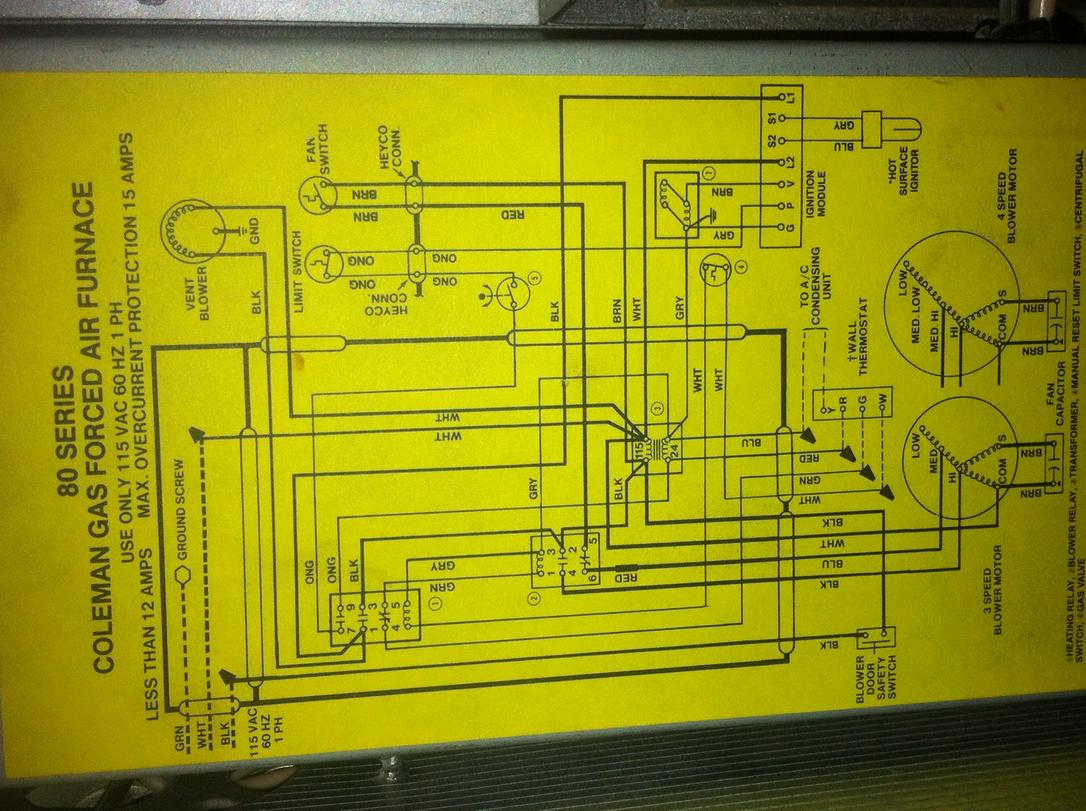
Finding Your Coleman Furnace Wiring Diagram
The wiring diagram is typically located:
- Inside the furnace control panel door.
- Attached to the inside of the furnace cabinet.
- In the furnace's installation manual.
If you can't find it, you may be able to find a similar diagram online by searching with your furnace's model number. Always verify the diagram matches your specific furnace model before using it for troubleshooting.
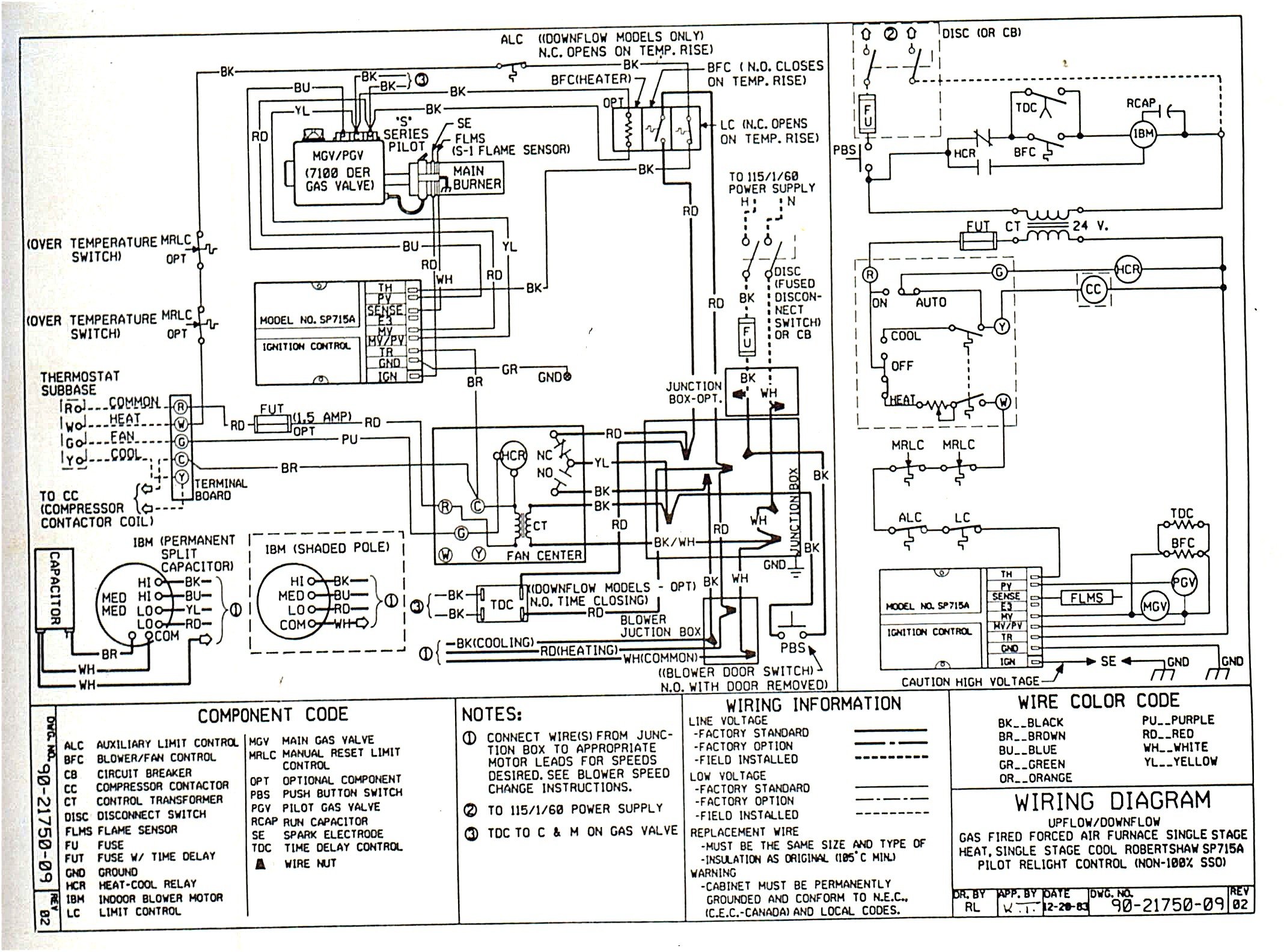
Decoding the Wiring Diagram
Wiring diagrams can seem intimidating at first, but they follow a set of conventions. Here's a breakdown:
Common Symbols and Abbreviations
- L1, L2: Line voltage (typically 120V in residential furnaces).
- N: Neutral.
- G: Ground.
- T-stat: Thermostat.
- M: Motor (e.g., blower motor, inducer motor).
- TR: Transformer.
- FS: Flame sensor.
- HS: High limit switch.
- PS: Pressure switch.
- TS: Temperature switch.
- IGN: Igniter.
- MV: Main gas valve.
- IND: Inducer motor.
- BLWR: Blower motor.
- XFMR: Transformer
Understanding Ladder Diagrams
Most furnace wiring diagrams are presented as ladder diagrams. Imagine a ladder with two vertical lines representing L1 and Neutral (or L2 depending on the diagram). The horizontal rungs of the ladder represent individual circuits. Each circuit usually controls a specific component or function.
The circuit is complete when there is a continuous path from L1 to Neutral (or L2) through all the components in that rung. A break in the circuit (e.g., a tripped switch, a blown fuse, a faulty component) will prevent the circuit from functioning.
Tracing a Circuit
Let's say you want to troubleshoot a non-functioning blower motor. Start by locating the blower motor (BLWR or M) on the wiring diagram. Trace the circuit back to the power source (L1 or L2) and through all the components in that circuit. This might include:
- A fuse or circuit breaker.
- A relay.
- A speed tap switch.
- A capacitor.
Test each component along the way to see if it's working correctly. Use a multimeter to check for voltage and continuity.
Common Coleman Furnace Components and Their Wiring
Transformer
The transformer (TR or XFMR) steps down the line voltage (120V) to a lower voltage (typically 24V) used by the control board and other components. It usually has a primary side connected to L1 and Neutral and a secondary side connected to the control board.
Control Board
The control board is the brain of the furnace. It receives signals from the thermostat and other sensors and controls the operation of the furnace. The wiring diagram will show all the connections to the control board, including the thermostat wires (R, W, G, Y, C), the flame sensor, pressure switch, limit switch, and other components.
Thermostat Wiring
The thermostat sends signals to the furnace to turn on the heat or cooling. The standard thermostat wires are:
- R: 24V power.
- W: Heat.
- G: Fan.
- Y: Cooling.
- C: Common (24V return).
The wiring diagram will show how these wires are connected to the control board.
Safety Switches
Furnaces have several safety switches to protect against overheating and other hazards. These switches are wired in series and must be closed for the furnace to operate. Common safety switches include:
- High Limit Switch (HS): Shuts off the furnace if it overheats.
- Pressure Switch (PS): Verifies that the inducer motor is creating sufficient draft.
- Flame Rollout Switch: Detects flames outside the combustion chamber.
Gas Valve
The gas valve controls the flow of gas to the burners. It's typically controlled by a 24V signal from the control board. The wiring diagram will show the connections to the gas valve and any safety switches in the circuit.
Igniter
The igniter (IGN) heats up to ignite the gas. It can be a hot surface igniter (HSI) or a spark igniter. The wiring diagram will show the connections to the igniter and the control board.
Troubleshooting with Your Wiring Diagram
Before troubleshooting, always turn off the power to the furnace at the circuit breaker.
No Heat
- Check the thermostat: Make sure it's set to heat and the temperature is set above the room temperature.
- Check the circuit breaker: Make sure the breaker for the furnace is not tripped.
- Check the flame sensor: A dirty flame sensor can prevent the furnace from staying lit. Clean it with fine steel wool.
- Check the high limit switch: If the furnace has overheated, the high limit switch may be tripped. Reset it manually (if it's a manual reset switch) or allow the furnace to cool down.
- Check the gas valve: Use a multimeter to check for voltage at the gas valve when the furnace is supposed to be heating.
- Check the igniter: Observe the igniter during startup. Is it glowing (HSI) or sparking (spark igniter)?
Blower Not Working
- Check the blower motor capacitor: A faulty capacitor can prevent the blower motor from starting.
- Check the blower motor relay: A faulty relay can prevent the blower motor from receiving power.
- Check the blower motor wiring: Look for loose or damaged wires.
Furnace Turns On and Off Quickly (Short Cycling)
- Check the high limit switch: Short cycling is often caused by overheating.
- Check the air filter: A dirty air filter can restrict airflow and cause the furnace to overheat.
- Check the ductwork: Make sure the ductwork is not blocked or restricted.
Safety Precautions
- Always turn off the power to the furnace at the circuit breaker before working on it.
- Label wires before disconnecting them to ensure they are reconnected correctly.
- Use a multimeter to test for voltage and continuity.
- Wear safety glasses and gloves.
- If you are not comfortable working with electricity, call a qualified HVAC technician.
When to Call a Professional
While some furnace problems can be addressed with basic troubleshooting, others require the expertise of a qualified HVAC technician. Call a professional if:
- You are not comfortable working with electricity or gas.
- You suspect a gas leak.
- You are unable to diagnose the problem.
- You are unsure how to repair the problem.
- The problem involves complex components like the control board or gas valve.
Estimating Repair Costs
Repair costs can vary depending on the problem and the cost of parts. Here are some rough estimates:
- Flame sensor replacement: $75 - $150
- Igniter replacement: $100 - $250
- High limit switch replacement: $80 - $200
- Gas valve replacement: $200 - $500
- Control board replacement: $300 - $700
- Blower motor replacement: $300 - $800
These are just estimates. Get a quote from a qualified HVAC technician for an accurate assessment of the repair costs.
Understanding your Coleman furnace wiring diagram can empower you to troubleshoot basic problems and communicate effectively with professionals. Remember to prioritize safety and consult a qualified technician for complex repairs. By taking a proactive approach to furnace maintenance, you can ensure a comfortable and safe home environment throughout the heating season.