Wiring Diagram For Dual Run Capacitor

The dual run capacitor is a critical component in many HVAC systems, particularly in air conditioners and heat pumps. It serves as an energy storage device, providing the necessary boost to start and run both the compressor motor and the fan motor. Understanding the wiring diagram for a dual run capacitor is essential for HVAC technicians to diagnose problems, perform maintenance, and ensure proper system operation. This article provides a comprehensive guide to dual run capacitor wiring diagrams, covering key concepts, troubleshooting tips, and career implications for HVAC professionals.
Understanding the Dual Run Capacitor
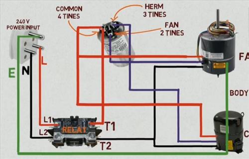
A dual run capacitor, sometimes called a "three-terminal capacitor," combines two capacitors in a single package. These two capacitors have different capacitance values and are used to power the compressor motor and the fan motor independently. The typical terminals on a dual run capacitor are:
- C (Common): This terminal is the common connection for both capacitors.
- HERM (Hermetically Sealed): This terminal is connected to the capacitor that powers the compressor motor.
- FAN: This terminal is connected to the capacitor that powers the fan motor.
The capacitance values are typically printed on the capacitor label, often in microfarads (µF). For example, a capacitor might be labeled "45/5 µF," indicating that the compressor capacitor is 45 µF and the fan capacitor is 5 µF.
Decoding the Wiring Diagram
Reading and understanding the wiring diagram associated with an HVAC unit that uses a dual run capacitor is paramount. While the specific diagram may vary depending on the manufacturer and model, certain elements remain consistent.
Typical Wiring Diagram Components
- Power Source: The diagram will show the incoming power lines (typically 220V or 240V in residential applications).
- Contactor: The contactor acts as a switch, controlled by the thermostat, to supply power to the outdoor unit.
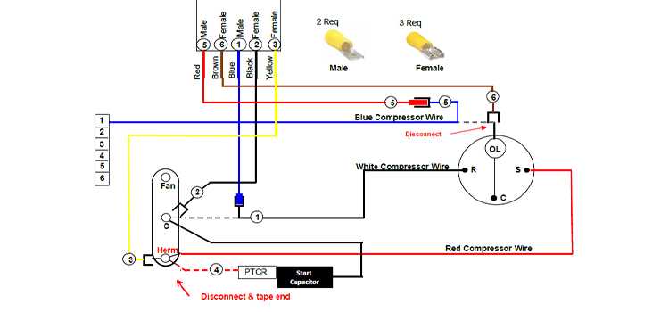
- Compressor Motor: The compressor motor is a three-phase or single-phase motor that compresses the refrigerant. The wiring diagram will show which terminal of the compressor connects to the HERM terminal of the capacitor.
- Fan Motor: The fan motor drives the condenser fan, which cools the refrigerant. The wiring diagram will show which terminal of the fan motor connects to the FAN terminal of the capacitor.
- Overload Protection: Overload protection devices, such as circuit breakers or fuses, are included to protect the motors from damage due to excessive current.
- Start Relay (Potential Relay): In some systems, a potential relay is used to assist in starting the compressor motor. This relay senses the voltage generated by the start winding and disconnects the start winding once the motor reaches a certain speed.
Reading the Diagram
Start by identifying the power source and tracing the wires to the contactor. When the thermostat calls for cooling, the contactor closes, supplying power to the outdoor unit. From the contactor, trace the wires to the dual run capacitor. The common terminal (C) of the capacitor will typically be connected to the common wire of the power supply. The HERM terminal will be connected to the run winding of the compressor motor, and the FAN terminal will be connected to the run winding of the fan motor. The wiring diagram will also show the connections for the start windings of the motors, which may involve a start relay or other starting components.
Troubleshooting with Wiring Diagrams
A thorough understanding of the wiring diagram is invaluable when troubleshooting HVAC systems. Here are some common issues and how the wiring diagram can help:
- Motor Not Starting: If either the compressor or the fan motor fails to start, the wiring diagram can help you trace the circuit and identify potential problems, such as a blown fuse, a faulty contactor, or a bad capacitor. Using a multimeter, you can check for voltage at various points in the circuit to pinpoint the location of the fault.
- Capacitor Failure: A bulging or leaking capacitor is a clear sign of failure. The wiring diagram helps you verify that the replacement capacitor has the correct capacitance values for the compressor and fan motors.
- Incorrect Wiring: If the system has been recently serviced or if components have been replaced, there is a possibility of incorrect wiring. The wiring diagram serves as a reference to ensure that all connections are made correctly.
- Short Circuits: Wiring diagrams show protective devices. Tripped breakers or blown fuses usually indicate a short circuit. The diagram will help you trace the circuit to find the cause of the short.
The Career Impact for HVAC Professionals
Proficiency in understanding and utilizing HVAC wiring diagrams, especially those involving dual run capacitors, significantly enhances the career prospects for HVAC technicians.
To excel in this field, consider the following:
Certifications
- NATE (North American Technician Excellence): NATE certification demonstrates a technician's knowledge and skills in HVAC. Specializations within NATE, such as air conditioning or heat pumps, further enhance credibility.
- EPA 608 Certification: Required by the Environmental Protection Agency (EPA) for technicians who handle refrigerants. This certification covers proper refrigerant handling, recovery, and disposal practices.
- Industry-Specific Training: Continuous training on new technologies, equipment, and diagnostic techniques is vital for career advancement.
Career Paths
An HVAC technician's career path can vary greatly depending on their interests and skill set. Some common career paths include:
- Residential HVAC Technician: Focuses on installing, maintaining, and repairing HVAC systems in homes.
- Commercial HVAC Technician: Works on larger, more complex HVAC systems in commercial buildings, such as offices, retail stores, and hospitals.
- HVAC Service Manager: Oversees a team of technicians and manages service operations.
- HVAC Design Engineer: Designs HVAC systems for new construction or renovation projects.
- HVAC Sales Engineer: Sells HVAC equipment and services to residential or commercial customers.
Real-World Examples
Consider the story of Maria, an HVAC apprentice who initially struggled with reading wiring diagrams. Through dedicated study and hands-on experience, she mastered the skill and became a highly sought-after technician known for her ability to quickly diagnose and repair complex HVAC systems. Her expertise led to promotions and increased earning potential.
Another example is John, a seasoned HVAC technician who obtained NATE certification to validate his skills and increase his marketability. The certification helped him secure a position as a commercial HVAC technician, where he worked on large-scale systems and earned a higher salary.
Best Practices
Here are some best practices when working with dual run capacitors and wiring diagrams:
- Safety First: Always disconnect power to the HVAC system before working on any electrical components. Use appropriate personal protective equipment (PPE), such as gloves and safety glasses.
- Double-Check: Verify the wiring diagram against the actual wiring in the unit before making any changes.
- Use a Multimeter: Use a multimeter to check for voltage, continuity, and capacitance.
- Document Your Work: Keep detailed records of your work, including the wiring diagram, the components you replaced, and any measurements you took.
- Stay Updated: Attend training sessions and workshops to stay updated on the latest HVAC technologies and diagnostic techniques.
Future Trends
The HVAC industry is constantly evolving, with new technologies and trends emerging. Some of the key trends to watch include:
- Smart HVAC Systems: Smart thermostats and other smart HVAC components are becoming increasingly popular. These systems offer features such as remote control, energy monitoring, and predictive maintenance.
- Variable Refrigerant Flow (VRF) Systems: VRF systems are energy-efficient systems that can provide customized heating and cooling to different zones in a building.
- Heat Pumps: Heat pumps are becoming more widely used as an energy-efficient alternative to traditional furnaces and air conditioners.
- Refrigerant Transition: New regulations are phasing out certain refrigerants with high global warming potential (GWP). Technicians need to be trained on handling new, more environmentally friendly refrigerants.
Conclusion
The ability to understand and interpret wiring diagrams, especially those involving dual run capacitors, is a fundamental skill for HVAC professionals. It enables accurate diagnosis, efficient repairs, and safe operation of HVAC systems. By investing in training, certifications, and continuous learning, HVAC technicians can enhance their career prospects and contribute to the growth of the industry.